
Outdoor Cook Stove

a technology for outdoor cooking and stoves, which is applied in the field of outdoor cooking stoves, can solve the problems of insufficient power of the grid, insufficient efficiency of the entire structure of the stove, and power is beyond the reach of single ring low pressure gas stoves, and achieves the effects of high power for wok cooking, simple burner construction, and significant cost saving

Inactive Publication Date: 2010-06-24
ZHOU DONGSHENG
View PDF7 Cites 14 Cited by
  • Summary
  • Abstract
  • Description
  • Claims
  • Application Information

AI Technical Summary

Benefits of technology

[0013]The first objective of the present invention is to utilize high pressure gaseous fuel to achieve highest power for wok cooking with simple burner construction to save cost significantly over traditional high power wok cookers with low pressure gaseous fuel.
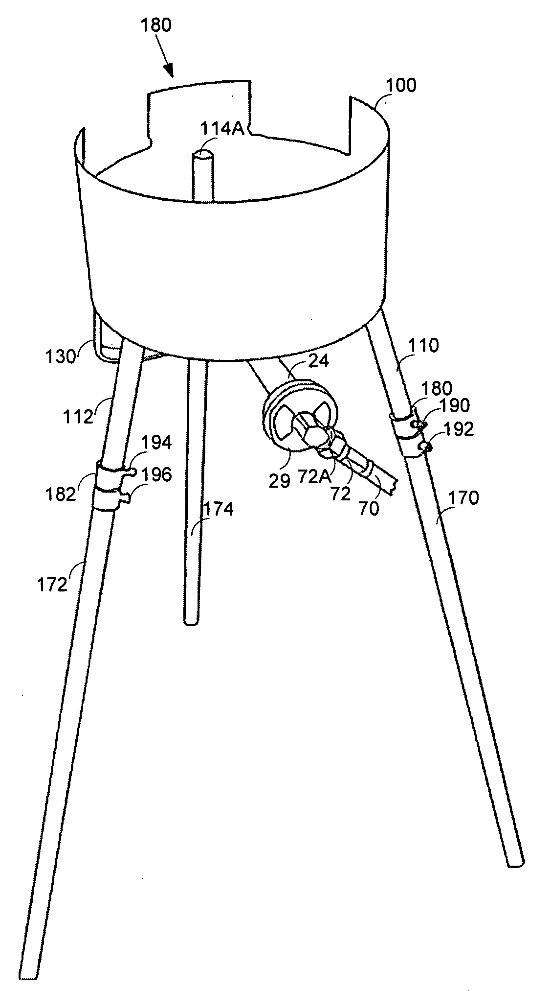
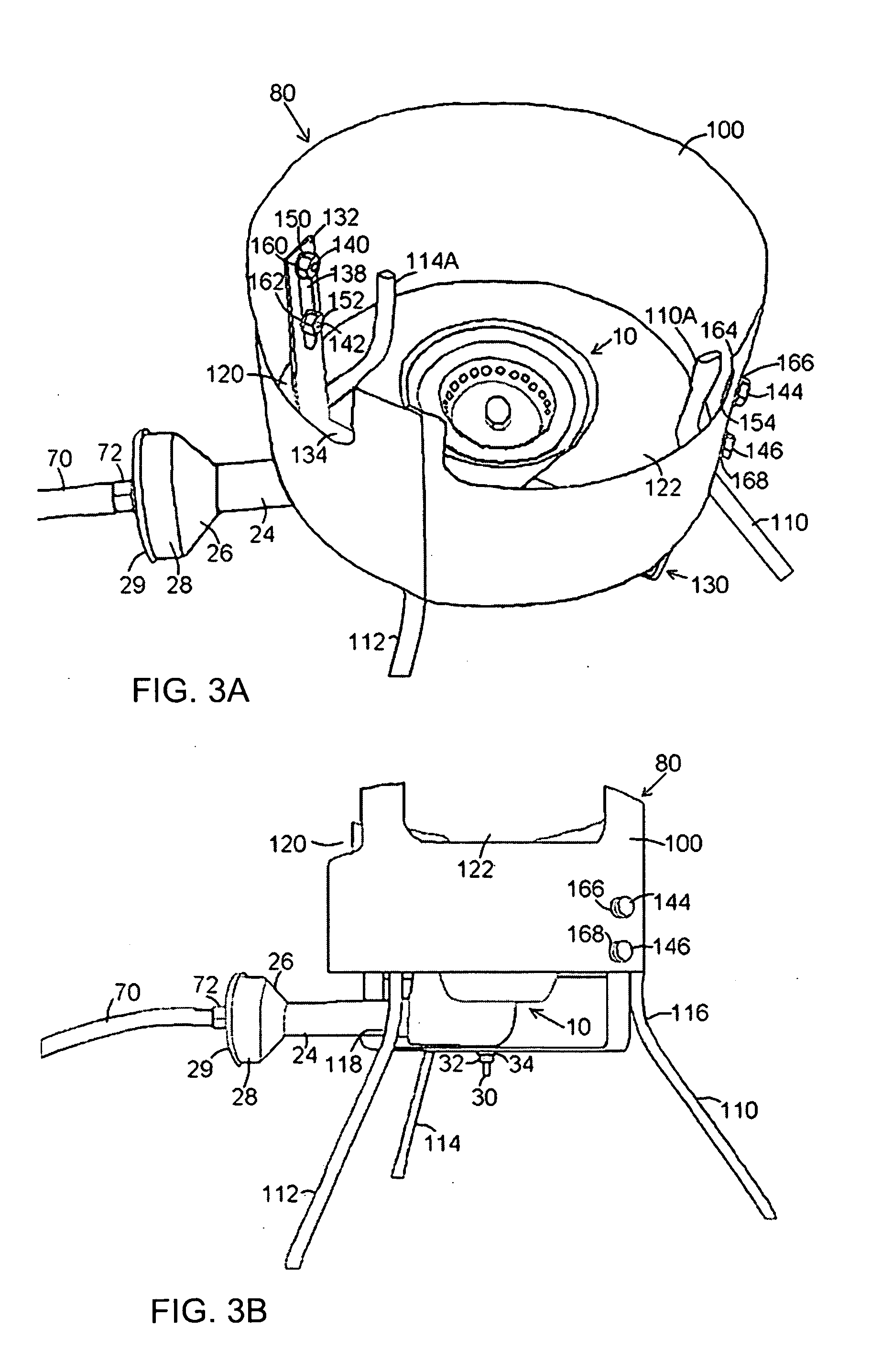
[0014]The second objective of the present invention is to construct an outdoor stove with a wind guard ring tightly hosting a wok. A portion of the wind guard has openings close to the wok for directing out the flame and exhaust. To increase cooking efficiency and product life cycle, such openings do not have top bars to block burner flamer from reaching underneath surface of the cooking vessel. It also provides access for burner ignition. This portion is to be positioned away from the operator during operation. The rest portion of the wind guard does not have opening to prevent any flame from extending along its side. The operator is positioned along this side for safe operation. This wind guard defines the heating area to the wok and is sized around 9″-13″ in diameter for commonly available woks.
[0015]The third objective of the present invention is to add a second ring outside the first wind guard to prevent the operator from accidentally touching the hot surface of the first wind guard.
[0016]The fourth objective of the present invention is to construct a stove to give complete freedom to the wok operator. The wok is not required to be fixed in position to the stove. The operator can tilt and move the wok in his / her own will at any time in order to achieve best cooking result.

Problems solved by technology

However the fire grid is not powerful enough and the entire structure is not efficient enough for wok cooking.
Such power is beyond reach of single ring low pressure gas stoves.
Another drawback of using low pressure gaseous fuel is its stove being more susceptible to wind during outdoor cooking.
However they share several disadvantages that prevent them from reaching high quality oriental cooking.
The second disadvantage is the low pressure burner which they utilize does not have center flame heating to the bottom of a wok.
The disadvantage of not using a center flame is in many burner designs, for example U.S. Pat. Nos. 6,234,064, 6,098,611, D386,936, 4,553,524, 4,353,347.
For a wok, this heat conducting downward to its bottom is extremely inefficient.
Yet another disadvantage of the aforementioned stove constructions is to allow the flame to extend above the wok along its outside surface.
Since wok cooking requires an operator to stay closely and maneuver the wok in different ways, the flame coming out can easily burn and hurt the operator.
Fixed position between stove and wok greatly restricts the freedom for the operator to tilt and rotate the wok for various food items to receive different flame power, which is necessary when the food items are too fragile to be tossed.
Another drawback is that as required by its inward flame, the burner has a bigger chamber for pre-mixed gaseous fuel and air.
This big chamber inevitably reduces the mixture gas pressure and hence the power of the burner.
This is wrap around wind screen is not study at all to withstand a round bottom vessel.
Besides, these top bars block the flame to reach the wok underneath surface.
This blockage is an efficiency loss.

Method used


Image

  • Outdoor Cook Stove
  • Outdoor Cook Stove
  • Outdoor Cook Stove

Examples


Embodiment Construction

[0018]The invention will now be described in connection with certain preferred embodiments with reference to the following illustrative figures so that it may be more fully understood.

[0019]With specific reference now to the figures in detail, it is stressed that the particular shown are by way of example and for purpose of illustrative discussion of the preferred embodiments of the present invention only. They are presented in the cause of providing what is believed to be the most useful and readily understood description of the principles and conceptual aspects of the invention. In this regard, no attempt is made to show structural details of the invention in more detail than is necessary for a fundamental understanding of the invention. The description together with the drawings should make it apparent for those skilled in the art how the several forms of the invention may be embodied in practice. In the drawings:

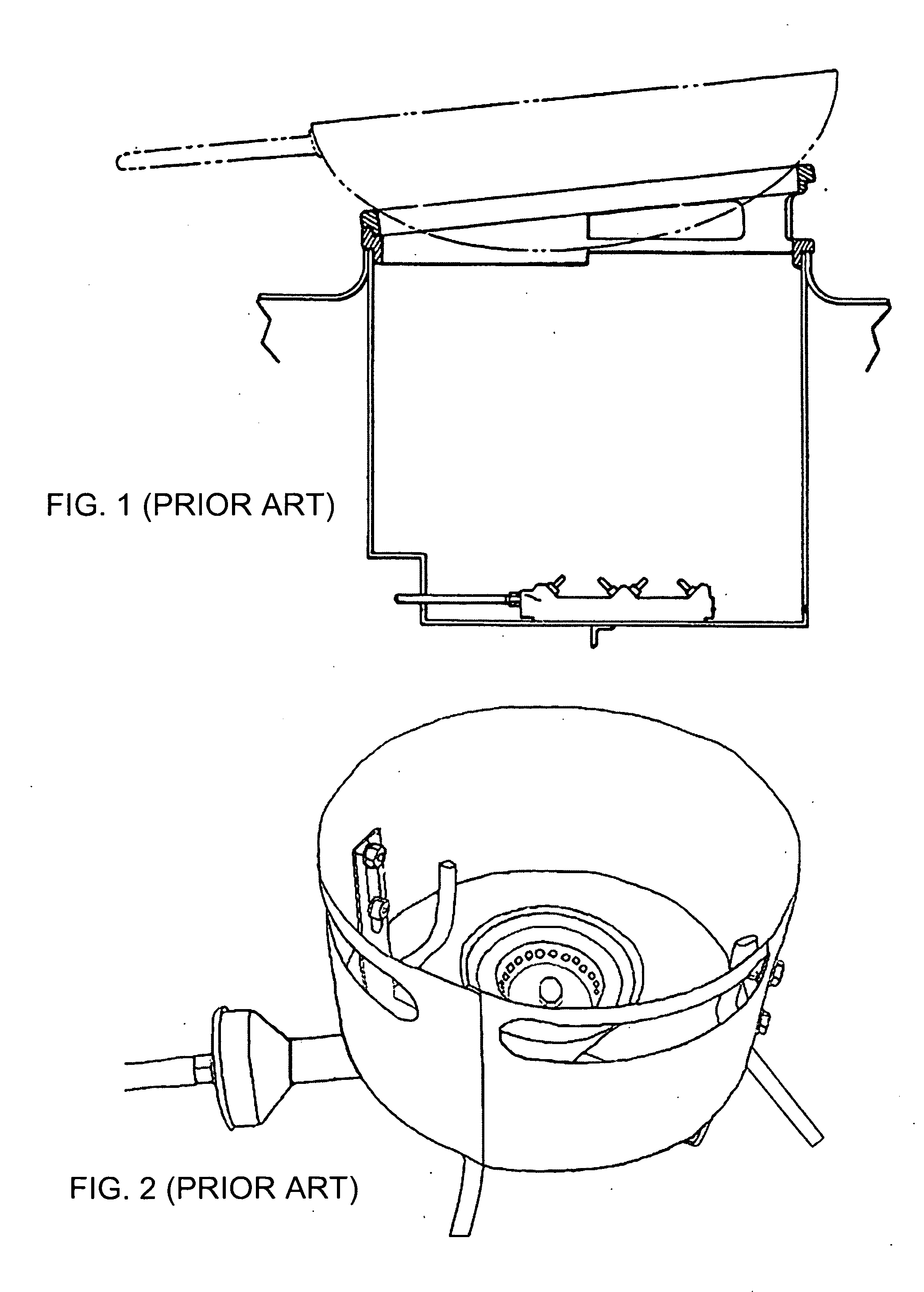
[0020]FIG. 1 is a prior art showing a two-piece support ring struct...


PUM


Abstract

A portable outdoor stove is provided which includes a burner primarily comprising an outer and inner pieces bolted tightly to form a small gas / air mixture chamber for accepting and maintaining high pressure gaseous fuel, a wind guard of cylinder shape capable of tightly coupled with a cooking vessel and possessing slot opening of less than 180° toward its top for exhaust outlet, adjustable means for supporting the burner and positioning flame from burner onto bottom of cooking vessel, short or long legs to support the wind guard and the cooking vessel. A protection guard can be put around the first wind guard preventing an operator accidentally touching the wind guard during cooking.

Description

[0001]US PATENT DOCUMENTS4,062,341December 1977Panzarella126 / 41 R5,158,067October 1992Dutro et al.126 / 39 R6,234,064May 2001Turrel 99 / 323.96,098,611August 2000Filmore126 / 50D386,936December 1997Stone et al.D7 / 3324,553,524November 1985Wheat et al.126 / 25 R4,353,347October 1982Seed126 / 41 R5,775,316July 1998Jones126 / 41 R4,555,616November 1985O'Brien219 / 4325,044,352September 1991Lok126 / 39 R5,226,406July 1993Reynolds126 / 39 R4,583,941April 1986Elperin et al. 41 / 3475,315,983May 1994Law126 / 2163,759,164September 1973Robinson 99 / 4134,108,142August 1978Barson et al.126 / 41 R5,992,407November 1999Tsai126 / 406,439,107August 2002Bourgeois 99 / 3406,725,856April 2004Barbour et al126 / 506,832,607December 2004Zhou126 / 306,619,280September 2003Zhou126 / 39 RBACKGROUND OF THE INVENTION[0002]1. Field of the Invention[0003]The present invention relates to an outdoor cook stove utilizing high pressure gaseous fuel, in particular a stove for domestic or industrial gas cooking using bottled gas, and is suitable for r...

Claims


Application Information

Patent Timeline
IPC IPC(8): F24C3/12F24C3/14
CPCF24C15/28F24C3/14F24C3/02
Inventor ZHOU, DONGSHENG
Owner ZHOU DONGSHENG
Learn More