Speaker mounting system

a technology for mounting systems and speakers, applied in the field of speaker mounting systems, can solve the problems of excessive unused space in the box of speakers, affecting the cost of shipping and warehousing as well as the cost of the product itself, and not an optimal situation

Active Publication Date: 2010-06-24
BOGEN COMM
View PDF9 Cites 6 Cited by
  • Summary
  • Abstract
  • Description
  • Claims
  • Application Information

AI Technical Summary

Benefits of technology

[0019]To prevent the clamp dog from rotating during insertion or removal of the component from the sheetrock or ceiling tile, the cap can be serrated on an external surface and the clamp

Problems solved by technology

However, including the tile bridge along with the speaker presents some packaging challenges due to the 24″ length of the tile bridge.
This leads to excessive unused space in the box of a speaker packaged to include the tile bridge.
This excessive space affects the cost of shipping and warehousing as well cost of the product itself.
Obviously, this is not an optimum situation, especially for speakers that may not be used in pairs.
The cost of these raw materials and the quantities in which they are used in a tile bridge significantly increases the cost of the product.
The location of the head of the screw actuator on the front of the speaker leads to some difficulties when assembling the speaker, ceiling tile and tile bridge together.
This leads to assembly difficulties since to actuate the screws, the assembly must be turned so the speaker is facing up, but then the ceiling tile and tile bridge fal

Method used


Image

  • Speaker mounting system
  • Speaker mounting system
  • Speaker mounting system

Examples


Embodiment Construction

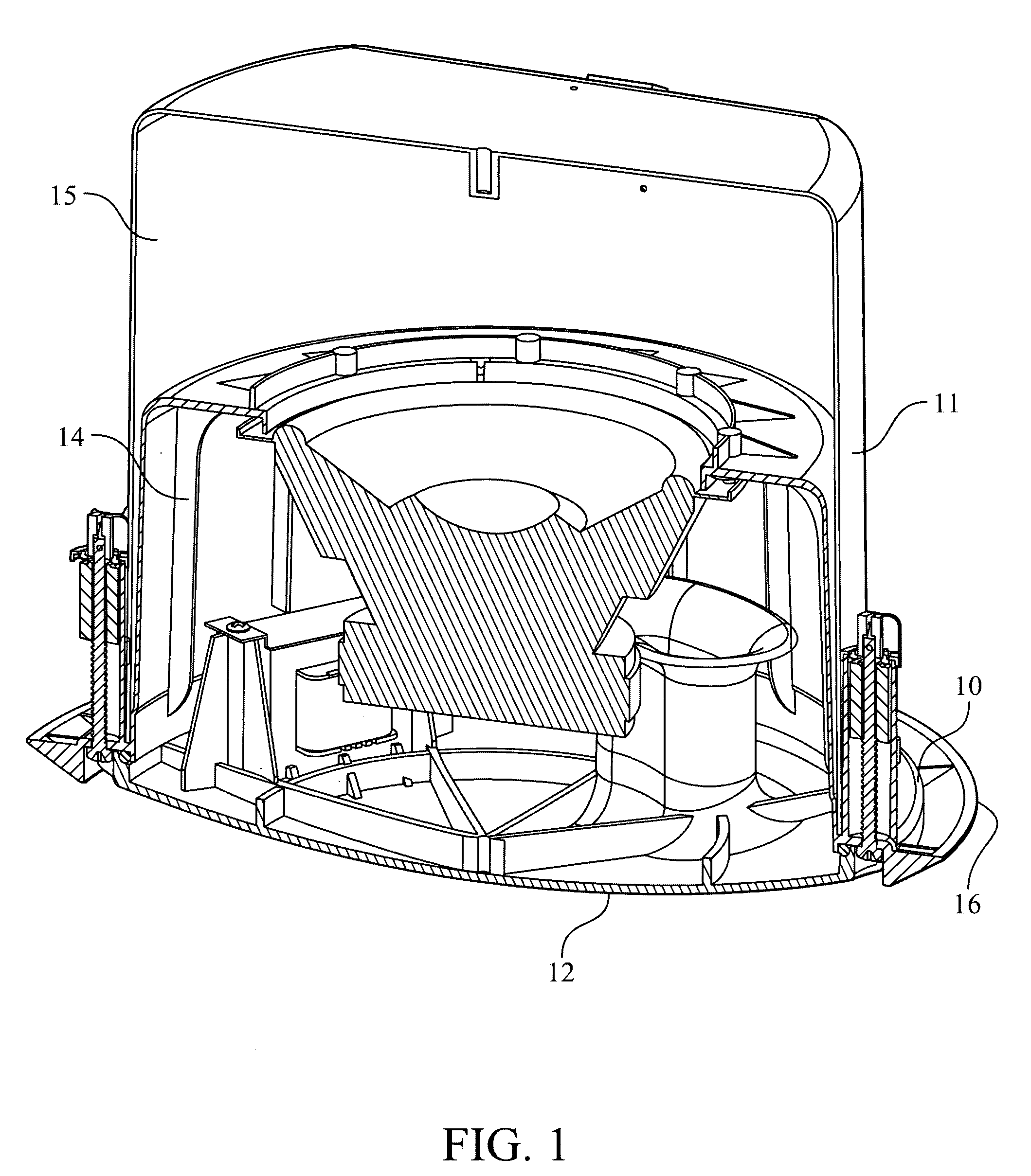
[0031]The embodiment shown in the drawings concerns a bandpass style subwoofer, but the invention is equally useful for many other speaker types and sizes. The subwoofer assembly as shown in FIG. 1 has a unique design where one molded cylindrical part 10 forms the mounting flange 16 and one half of a chamber 14. A cylindrical metal back-can 11 encloses this part and forms a second chamber 15. A ported cover 12 completes the first chamber. Back-can 11 has an angled terminal entry with flush cover to fit tight spaces.

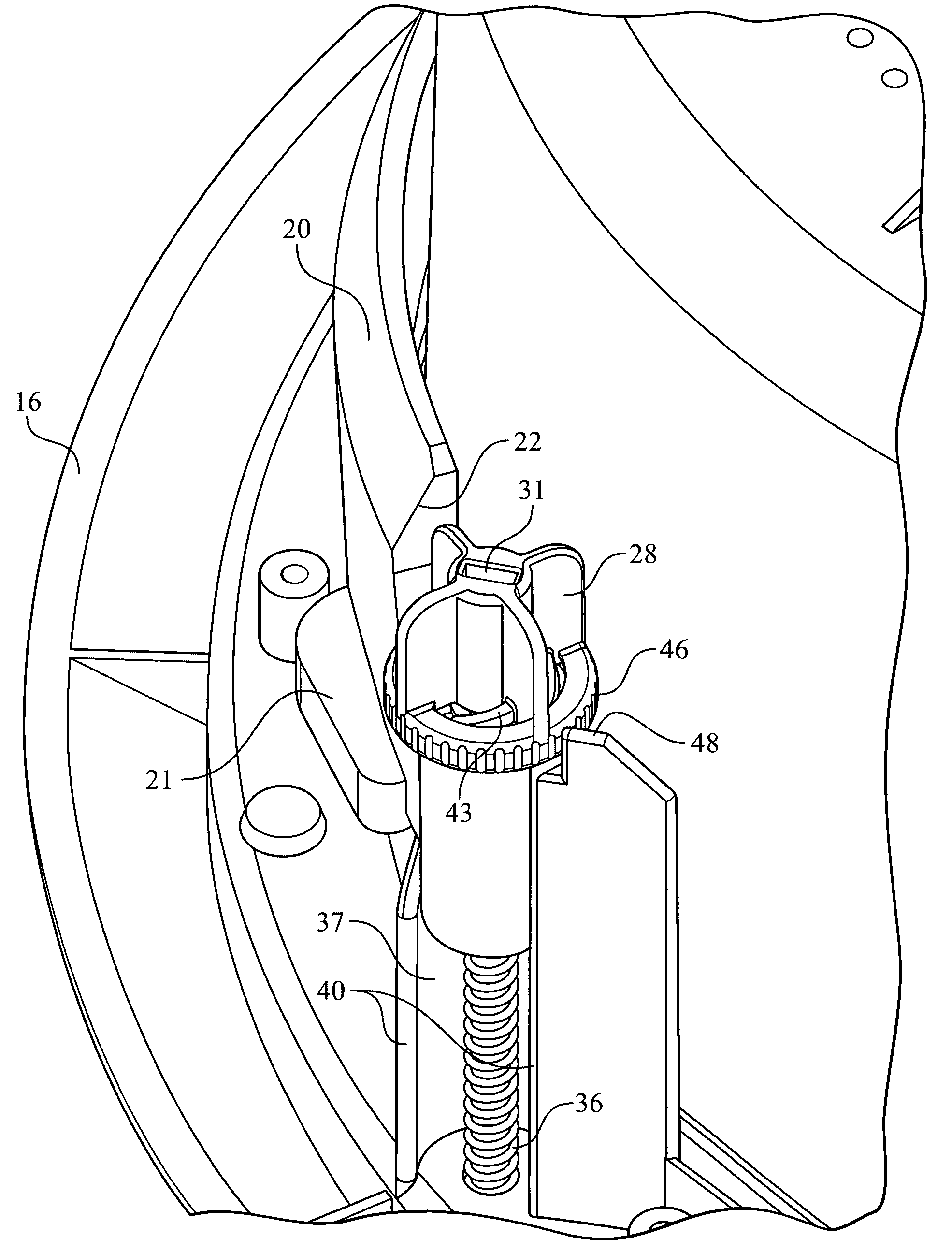
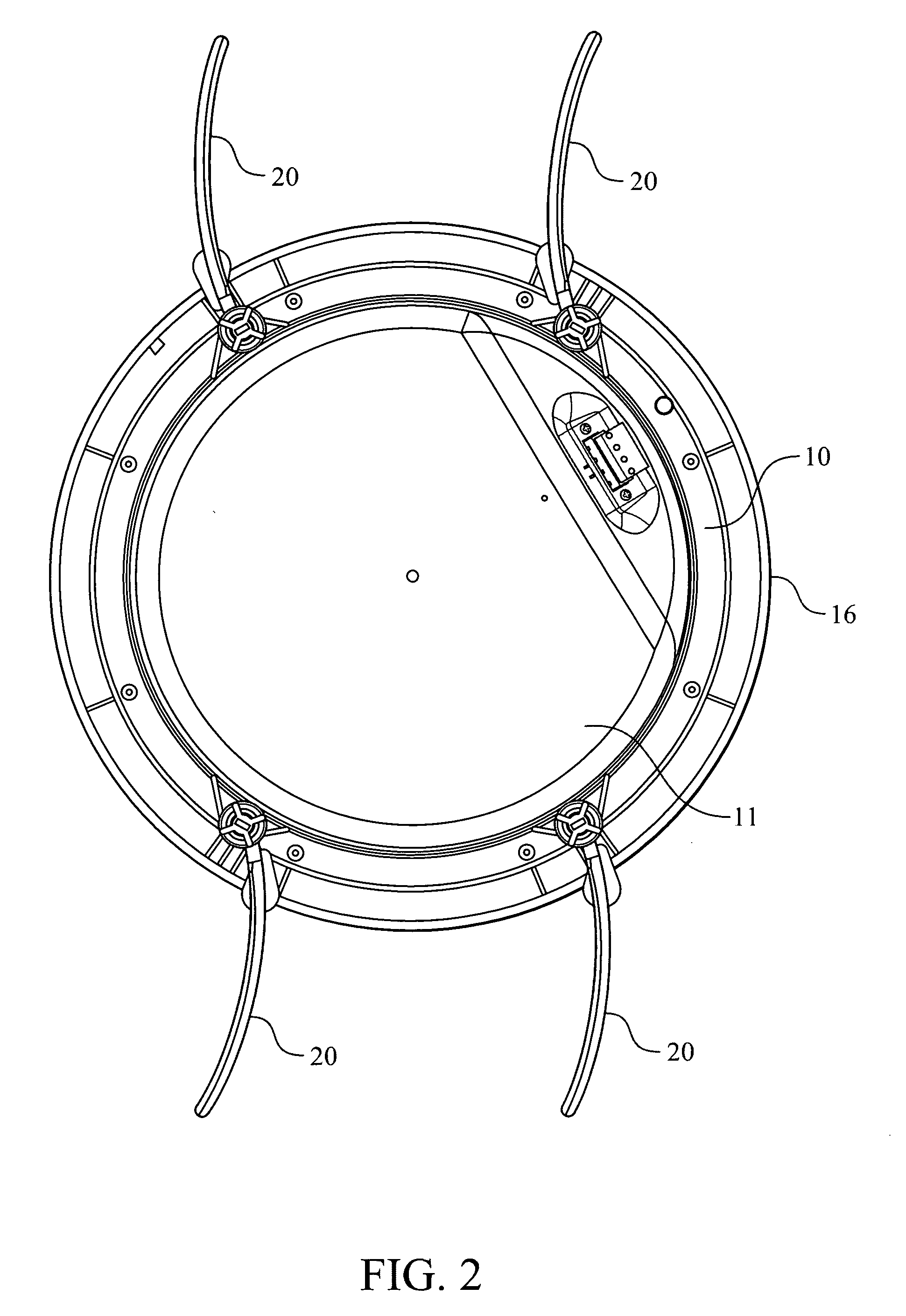
[0032]To eliminate the need for a separate tile bridge, four long clamp dogs 20 as shown in FIGS. 2 and 3, are connected to mounting flange 16 of the speaker. These are curved to fit tightly to the cylindrical metal back can 11 so the product assembly can be installed through the smallest possible mounting hole 51 in a ceiling tile 50, as shown in FIG. 7. Two of these clamp dogs 20 are placed close together, forming two pairs. This keeps their length to a minimum by getti...


PUM


Abstract

A system for mounting a component in an aperture of a supporting surface has a mounting flange surrounding the component to be mounted, and at least two clamp dogs attached to the mounting flange and located adjacent a rear surface of the mounting flange. The component is inserted into a mounting hole cut in a sheet rock surface or ceiling tile, so that the flange abuts the front face of the surface. The clamping assemblies are located on the rear face of the surface. There is a pivoting system for pivoting the clamp dog around an axis. The pivoting system is operable from both the front surface and the rear surface of the mounting flange so that the clamp dogs can be actuated from either side of the sheet rock or ceiling tile.

Description

BACKGROUND OF THE INVENTION[0001]1. Field of the Invention[0002]The present invention relates to a speaker mounting system that eliminates the need for a tile bridge.[0003]2. The Prior Art[0004]High quality speakers designed for mounting in suspended ceilings commonly comprise a front bezel and grill and have a back-can that fully encloses all the parts of the speaker assembly. The back-can, in addition to its acoustic purpose, protects the speaker and other components from dust and damage as well as often acting as a fire block. Back-cans are typical but not always required. Mounting these types of speakers in a suspended ceiling tile usually requires an additional bracket, commonly referred to as a tile bridge, to transfer the speaker's weight onto the suspended ceiling grid structure and off of the non-load bearing ceiling tiles. A tile bridge is required to rigidly span the entire width of the ceiling tile. The typical tile bridge has two structural rails to span the tile width ...

Claims


Application Information

Patent Timeline
IPC IPC(8): A47B96/06A47F5/08
CPCH04R1/025Y10S248/916
Inventor NELSON, THOMASKETTERER, ERNEST
Owner BOGEN COMM
Why Eureka
Try Eureka