Method of quick charging lithium-based secondary battery and electronic device using same

a lithium-based secondary battery and electronic device technology, applied in secondary cell servicing/maintenance, instruments, cell components, etc., can solve the problems of insufficient charging time and actual battery cannot be charged up to a full charge, and achieve the effect of quick charging and preventing overcharging

Inactive Publication Date: 2010-06-24
PANASONIC CORP
View PDF8 Cites 66 Cited by
  • Summary
  • Abstract
  • Description
  • Claims
  • Application Information

AI Technical Summary

Benefits of technology

[0005]It is an object of the present invention to provide a quick charging method of a lithium-based secondary battery by which quick charging up to a full charge can be performed, while preventing overcharging.
[0009]Therefore, a constant high current can be supplied from the beginning of charging to the end and quick charging can be performed, while preventing overcharge.

Problems solved by technology

However, even if a voltage of 4.2 V is applied, as mentioned hereinabove, the voltage that actually contributes to charging is less than this value due to the effect of internal resistance, and the battery actually cannot be charged up to a full charge.
The problem associated with the above-described conventional related art is that charging is performed up to a full charge, while preventing overcharge, by substantially reducing the charging current in the final period of charging and, therefore, the reduction of charging time is insufficient.

Method used


Image

  • Method of quick charging lithium-based secondary battery and electronic device using same
  • Method of quick charging lithium-based secondary battery and electronic device using same
  • Method of quick charging lithium-based secondary battery and electronic device using same

Examples


embodiment 1

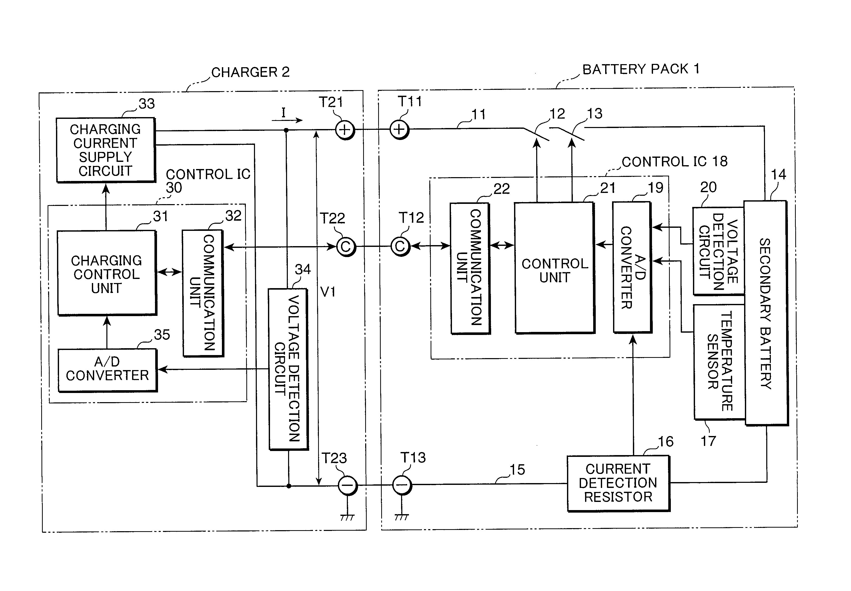
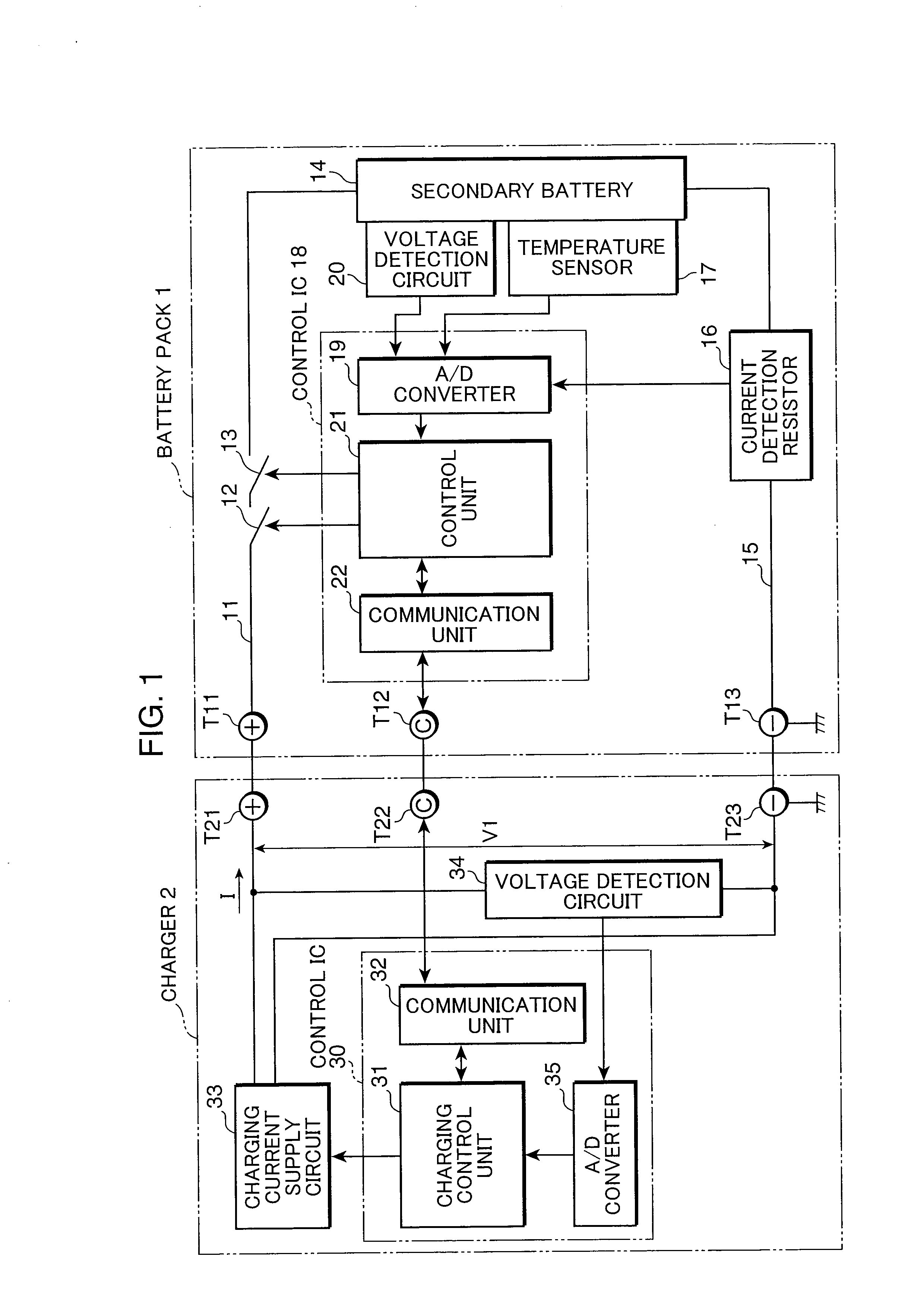
[0024]FIG. 1 is a block diagram illustrating the electric configuration of the electronic device of Embodiment 1 of the present invention. This electronic device is constituted by providing a charger 2 that charges a battery pack 1 and a load device (not shown in the figure) in the battery pack. In the configuration shown in FIG. 1, the battery pack 1 is charged from the charger 2, but it is also possible to mount the battery pack 1 on the load device and charge the battery pack via the load device. The battery pack 1 and charger 2 are connected to each other by terminals T11, T21 on the DC-high side that conduct power supply, terminals T12, T22 for communication signals, and GND terminals T13, T23 for power supply and communication signals. Same terminals are provided even when the load device is not provided.

[0025]FET 12, 13 that have mutually different conductivity modes for charging and discharging are introduced in a charge-discharge path 11 on a DC-high side that extends from ...

embodiment 2

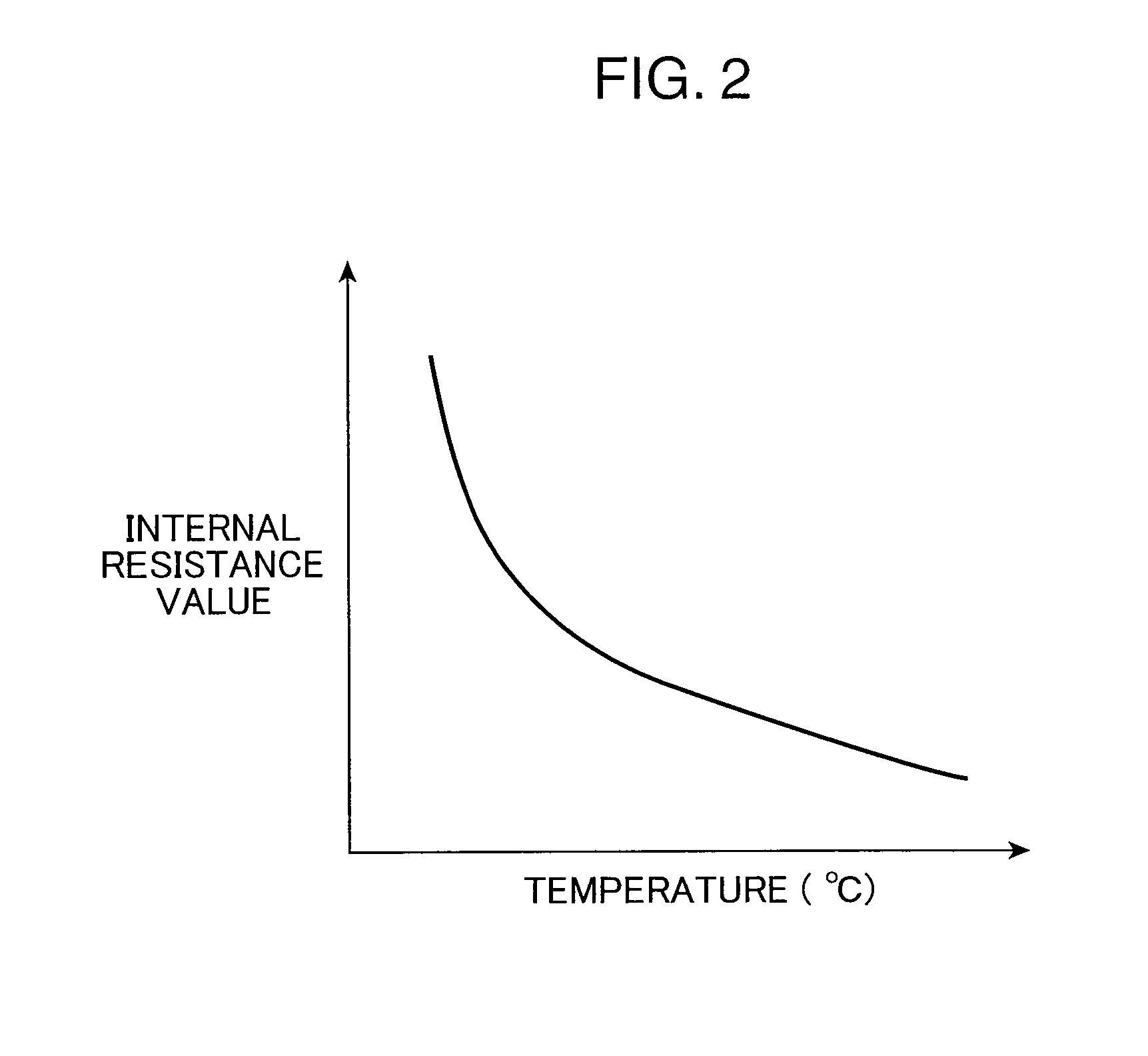
[0042]FIG. 5 is a flowchart illustrating in detail the charging operation in the electronic device according to Embodiment 2 of the present invention. In this embodiment, the above-described configuration of electronic device shown in FIG. 1 can be used. The processing illustrated by FIG. 5 is similar to the above-described processing illustrated by FIG. 3, and the corresponding portions are assigned with identical step numbers and explanation thereof is herein omitted. A noteworthy feature of the present embodiment, it that that the charge end voltage Vf′ is determined not only by the internal resistance value R, but also by taking into account the terminal voltage V1 and actual capacity W of the secondary battery 14. As shown in FIG. 2, the internal resistance value R (DC-IR) not only decreases with the increase in temperature, but also changes depending on SOC (State of Charge), as shown in FIG. 6. Further, the internal resistance value R increases as the deterioration advances d...

embodiment 3

[0050]FIG. 8 is a block diagram illustrating a configuration example of the electronic device of Embodiment 3 of the present invention. In FIG. 8, components identical to those of the electronic device shown in FIG. 1 are assigned with identical reference numerals and explanation thereof is omitted. The electronic device shown in FIG. 8 differs from the electronic device shown in FIG. 1 in the aspects as follows. Thus, in the electronic device shown in FIG. 8, a control unit 21a functions as a charging control unit 210, an internal resistance estimation unit 211, and a charge end voltage calculation unit 212.

[0051]The charging control unit 31a dose not performs the detection of the internal resistance value R, setting of the charge end voltage, and determination of charge end. Further, a load device 4 is connected between a terminal T21 and a terminal T23. The discharge current of the secondary battery 4 and the current outputted from the charging current supply circuit 33 is suppli...


PUM

PropertyMeasurementUnit
voltageaaaaaaaaaa
negative electrode potentialaaaaaaaaaa
charge voltageaaaaaaaaaa

Abstract

A charging current is maintained at a predetermined constant quick charging current (S1) and a full charge determination is made at a point in time (S7) when the terminal voltage (V1) (S6) reaches the charge end voltage Vf′. The charge end voltage Vf′ is taken as a voltage (S5) obtained by adding a voltage drop amount VD (S4) that is obtained by multiplying an internal resistance value (S3) estimated from the temperature T (S2) of a secondary battery by a quick charging current value to a predetermined initial charge end voltage Vf. Therefore, a constant high current can be supplied from the beginning to the end and quick charging can be performed up to a full charge, while preventing overcharge, in place of the conventional CC-CV charging.

Description

TECHNICAL FIELD[0001]The present invention relates to a method for quick charging of a lithium-based secondary battery and an electronic device using same.BACKGROUND ART[0002]A CCCV (Constant Current Constant Voltage) charging method, for example, such as illustrated by FIG. 7, is known as a representative conventional method for charging a lithium-based secondary battery. With a standard CCCV charging method, first, the CC (constant current) charging is performed at a current of about 0.7 to 1 C, where a current value at which a fully charged battery can be discharged to a SOC (State Of Charge) of 0% in 1 hour is taken as 1 C. Then, after a terminal voltage of the battery becomes a predetermined charge end voltage, for example 4.2 V, the charging mode is switched to CV (constant voltage) charging that the charging current is reduced so as to maintain the charge end voltage. FIG. 7A is a graph illustrating the variation in cell voltage, and FIG. 7B is a graph illustrating the variat...

Claims


Application Information

Patent Timeline
Patent Type & Authority Applications(United States)
IPC IPC(8): H02J7/00G01R31/36H01M4/02H01M4/13H01M10/44H01M50/443H01M50/489H02J7/10
CPCH01M2/16H01M2/168H01M10/052Y02E60/122H01M10/448H02J7/0091H01M10/443H01M10/44H01M10/46Y02E60/10H01M50/461H02J7/007194H01M50/443H01M50/489G01R31/36H02J7/04
Inventor ASAKURA, JUNIIDA, TAKUMANISHINO, HAJIME
Owner PANASONIC CORP
Why Eureka
Try Eureka