
Lubricant deterioration detecting device and detecting device incorporated bearing assembly

a technology of detecting device and bearing assembly, which is applied in the direction of mechanical equipment, instruments, transportation and packaging, etc., can solve the problems of deterioration of lubricant, reduced life of bearing assembly, and inability to detect the presence or absence of abnormality in lubrication, etc., and achieves high accuracy

Inactive Publication Date: 2010-06-24
NTN CORP
View PDF19 Cites 51 Cited by
  • Summary
  • Abstract
  • Description
  • Claims
  • Application Information

AI Technical Summary

Benefits of technology

[0008]An object of the present invention is to provide a lubricant deterioration detecting device capable of detecting the status of deterioration of the lubricant with high accuracy and also to provide a detecting device incorporated bearing assembly capable of detecting the status of deterioration of the lubricant accurately and in real time.

Problems solved by technology

In the bearing assembly filled with a lubricant, an insufficient lubrication occurs once the lubricant (such as, for example, a grease or oil) within the bearing assembly is deteriorated, resulting in a reduction in lifetime of the bearing assembly.
Determination of the occurrence of the insufficient lubrication in reference to the status of vibration occurring in the bearing assembly is carried out when and after an operating abnormality has occurred as a result of expiration of the lifetime of the bearing assembly and is, accordingly, incapable of detecting the presence or absence of an abnormality in lubrication at an early stage.
A major cause of deterioration of the lubricant may be enumerated an admixture of a powdery wear debris, which is produced as the bearing assembly is used, with the lubricant.
However, since the sensor incorporated bearing assembly disclosed in the above mentioned patent document is so designed that the electrical characteristic of the lubricant can be detected, no change in characteristic can be detected unless a condition is established in which conduction occurs as a result of inclusion of a substantial amount of wear debris and, thus, difficulty often occurs in detecting the inclusion of the alien substance.

Method used


Image

  • Lubricant deterioration detecting device and detecting device incorporated bearing assembly
  • Lubricant deterioration detecting device and detecting device incorporated bearing assembly
  • Lubricant deterioration detecting device and detecting device incorporated bearing assembly

Examples


first embodiment

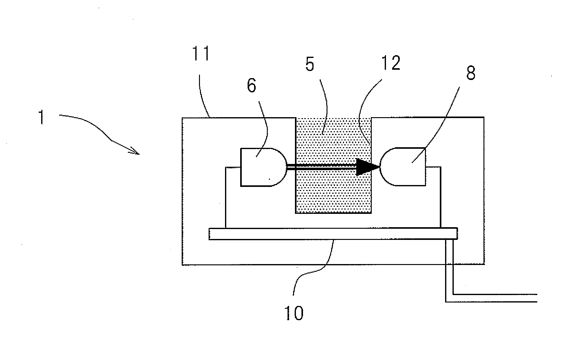
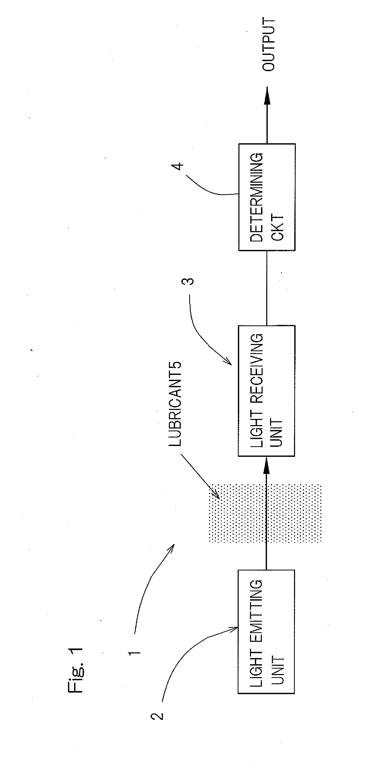
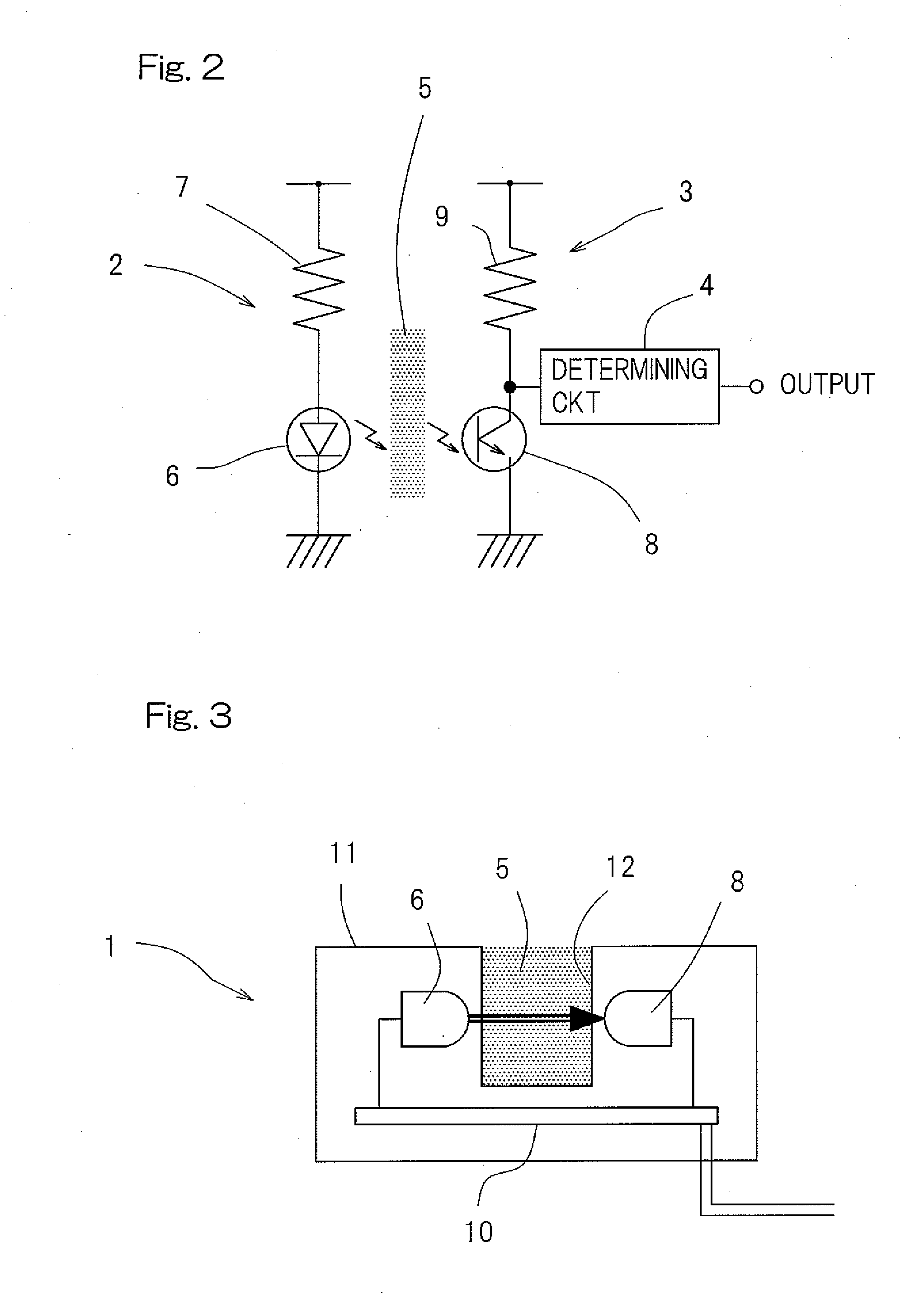
[0065]A first preferred embodiment of the present invention will be described with particular reference to FIGS. 1 to 4. FIG. 1 illustrates a diagram showing the principle construction of the lubricant deterioration detecting device according to this This lubricant deterioration detecting device 1 includes a light emitting unit 2 and a light receiving unit 3 defining a gap therebetween for accommodating a lubricant 5, which forms an object to be detected, intervening therebetween, and a circuit in the form of a determining circuit 4 for determining the light transmittance of the lubricant 5 in reference to an output of the light receiving unit 3 to thereby detect the amount of alien substances admixed in the lubricant 5. The light emitting unit 2 includes a light emitting element 6 such as, for example, a light emitting diode and the light receiving unit 3 includes a light receiving element 8 such as, for example, a phototransistor.

[0066]FIG. 2 illustrates an example of a specific ...

eighth embodiment

[0100]FIG. 15 illustrates a schematic structural diagram showing a tenth preferred embodiment of the present invention. The lubricant deterioration detecting device 1 according to this embodiment is similar to that shown in and described with reference to FIGS. 12 and 13, but differs therefrom in that the respective ends 18a and 19b of the light emitting and receiving optical fibers 18 and 19, both of which are on the side confronting the lubricant 5, are so arranged as to confront the lubricant 5 through associated mirrors 23A and 23B. More specifically, the end 18a of the light emitting optical fiber 18 is provided with the mirror 23A so that rays of light emitted therefrom can be transmitted across the lubricant 5 after having been deflected at right angles by the mirror 23A. Similarly, the end 19a of the light receiving optical fiber 19 is provided with the mirror 23B so that the rays of light having passed across the lubricant 5 via the mirror 23A can enter the end 19a of the ...


PUM


Abstract

A lubricant deterioration detecting device has a light emitting unit and a light receiving unit so arranged as to define a gap therebetween for accommodating a lubricant forming an object to be detected, and a determining circuit for determining a light transmittance of the lubricant in reference to an output from the light receiving unit to thereby detect a status of deterioration of the lubricant.

Description

BACKGROUND OF THE INVENTION[0001]1. Field of the Invention[0002]The present invention relates to a lubricant deterioration detecting device for detecting the status of deterioration a lubricant resulting from admixture of an alien substance and also to a detecting device incorporated bearing assembly equipped with such lubricant detection detecting device such as, for example, a lubricant deterioration detecting device incorporated bearing assembly for use in railway vehicles, automotive vehicles and industrial machines or the like.[0003]2. Description of the Prior Art[0004]In the bearing assembly filled with a lubricant, an insufficient lubrication occurs once the lubricant (such as, for example, a grease or oil) within the bearing assembly is deteriorated, resulting in a reduction in lifetime of the bearing assembly. Determination of the occurrence of the insufficient lubrication in reference to the status of vibration occurring in the bearing assembly is carried out when and afte...

Claims


Application Information

Patent Timeline
IPC IPC(8): G01N21/59
CPCF16C19/52F16C33/6674G01N33/2888G01N21/532G01N21/534G01N21/31F16C19/386F16C2326/10
Inventor TAKAHASHI, TORUNAKAJIMA, AKIOMAEDA, KAZUNARISUZUKI, KOUYOU
Owner NTN CORP
Features
  • Generate Ideas
  • Intellectual Property
  • Life Sciences
  • Materials
  • Tech Scout
  • Unparalleled Data Quality
  • Higher Quality Content
  • 60% Fewer Hallucinations
Learn More