

Heat-transporting device, electronic apparatus, and method of producing a heat-transporting device
a heat-transporting device and electronic equipment technology, applied in the direction of lighting and heating equipment, instruments, and semiconductor/solid-state device details, etc., can solve the problems of increased flow path resistance, reduced capillary force, and difficulty in enhancing heat-transporting performance, so as to achieve high heat-transporting performance and reduce costs
- Summary
- Abstract
- Description
- Claims
- Application Information
AI Technical Summary
Benefits of technology
Problems solved by technology
Method used
Image

Examples
first embodiment
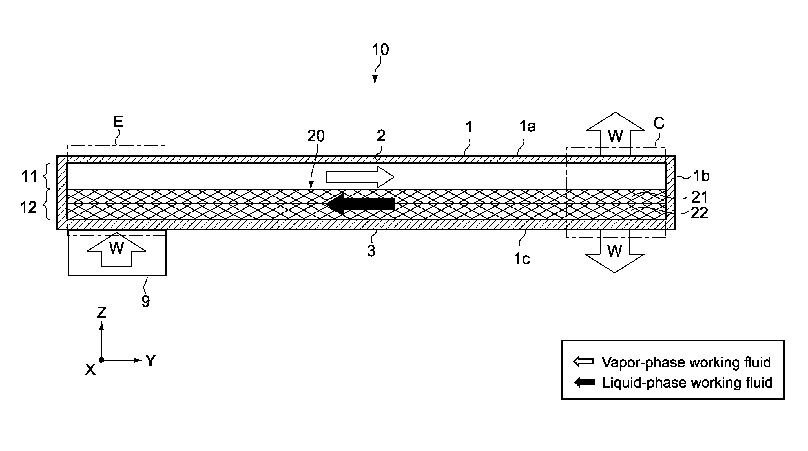
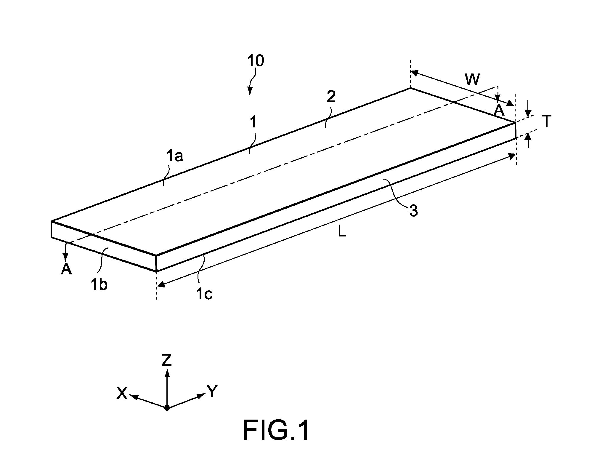
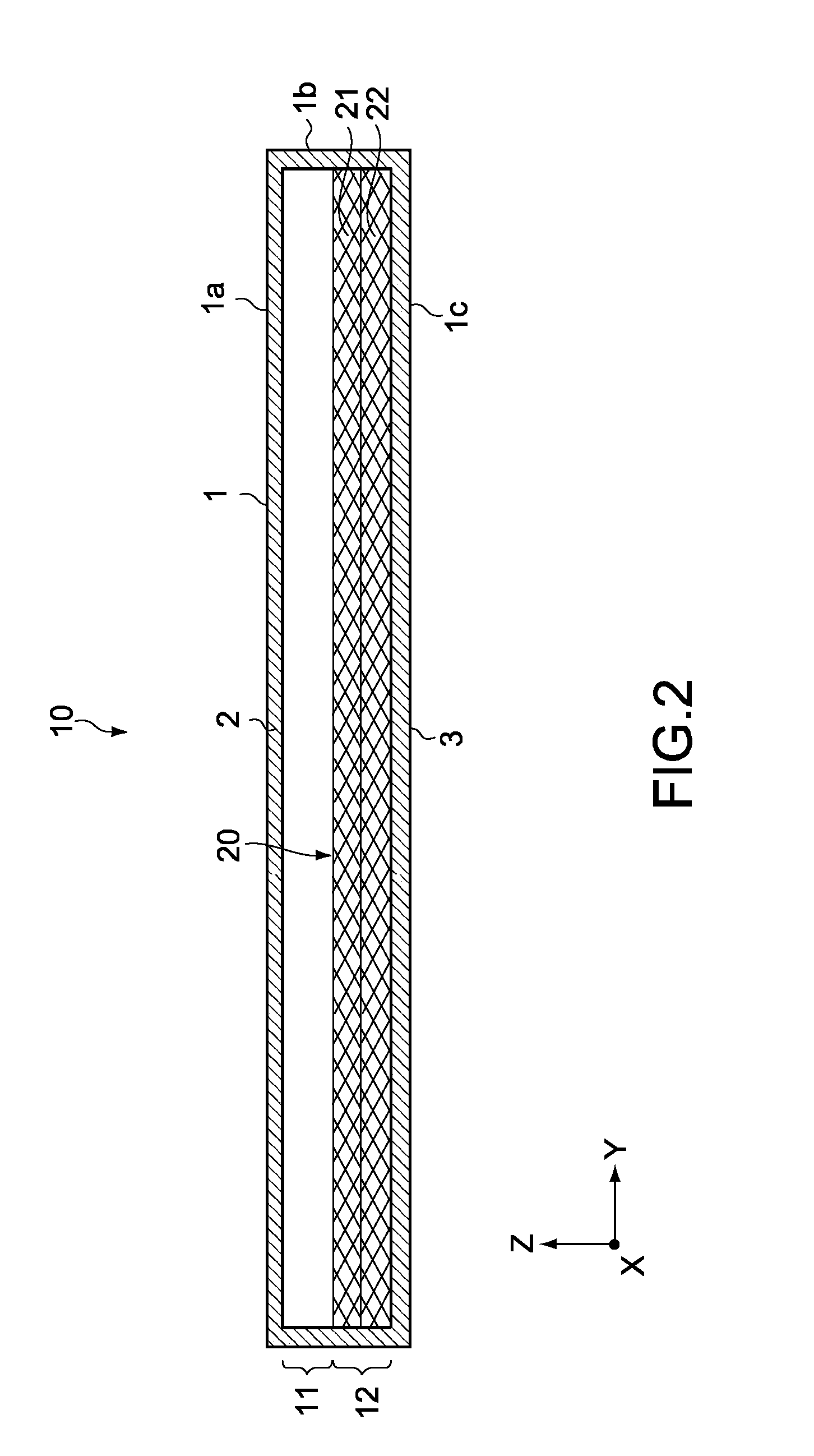
[0128]FIG. 1 is a perspective view of a heat-transporting device according to a first embodiment. FIG. 2 is a cross-sectional side view of the heat-transporting device taken along the line A-A of FIG. 1. It should be noted that in the specification, for brevity of descriptions on the figures, a heat-transporting device, components of the heat-transporting device, and the like may be illustrated in sizes different from actual sizes thereof.
[0129]As shown in the figures, a heat-transporting device 10 includes a thin rectangular plate-like vessel 1 that is elongated in one direction (y-axis direction). The vessel 1 is formed by bonding an upper plate member 2 that constitutes an upper portion 1a of the vessel 1 and a lower plate member 3 that constitutes a circumferential side portion 1b and a lower portion 1c of the vessel 1. A concave portion is formed in the lower plate member 3, and the concave portion forms a space inside the vessel 1.
[0130]Typically, the upper plate member 2 and ...
second embodiment
[0172]Next, a second embodiment of the present invention will be described.
[0173]The first embodiment above has described a case where the liquid-phase flow path 12 is formed by laminating two mesh members 21 and 22. In the second embodiment, however, the liquid-phase flow path 12 is formed by laminating three mesh members. Therefore, that point will mainly be described. It should be noted that in descriptions below, members having the same structures and functions as those of the first embodiment above are denoted by the same symbols, and descriptions thereof will be omitted or simplified.
[0174]FIG. 8 is a cross-sectional side view of a heat-transporting device according to the second embodiment.
[0175]As shown in FIG. 8, a heat-transporting device 50 of the second embodiment includes a laminated body 30 that has three mesh members 31 to 33. In descriptions below, out of the three mesh members, the mesh member 31 as an upper layer will be referred to as upper-layer mesh member 31, t...
third embodiment
[0181]Next, a third embodiment of the present invention will be described.
[0182]The above embodiments have described cases where the vapor-phase flow path 11 is hollow. However, a heat-transporting device according to the third embodiment is provided with columnar portions 5 in the vapor-phase flow path. Therefore, that point will mainly be described. It should be noted that in descriptions on the third embodiment and subsequent embodiments, points different from those of the second embodiment will mainly be described.
[0183]FIG. 10 is a perspective view of a heat-transporting device according to the third embodiment. FIG. 11 is a cross-sectional diagram taken along the line A-A of FIG. 10.
[0184]As shown in the figures, in a heat-transporting device 60, the liquid-phase flow path 12 is constituted of three mesh members 31 to 33 and the vapor-phase flow path 11 is provided with a plurality of columnar portions 5. The plurality of columnar portions 5 are arranged in the x- and y-axis d...
PUM
| Property | Measurement | Unit |
|---|---|---|
| Angle | aaaaa | aaaaa |
| Angle | aaaaa | aaaaa |
| Force | aaaaa | aaaaa |
Abstract
Description
Claims
Application Information