Movable body apparatus, exposure apparatus, exposure method, and device manufacturing method

a technology of movable bodies and equipment, applied in the direction of process and machine control, printing, instruments, etc., can solve the problem that the control system cannot unfailingly control the position of the movable body in a wide range within the two-dimensional plan

Active Publication Date: 2010-06-24
NIKON CORP
View PDF87 Cites 37 Cited by
  • Summary
  • Abstract
  • Description
  • Claims
  • Application Information

AI Technical Summary

Benefits of technology

[0021]According to the method, it becomes possible to measure the positional information of the movable body within a broad range including

Problems solved by technology

Accordingly, the control system can unfailingly control the position of the movable body in a wide range within t

Method used


Image

  • Movable body apparatus, exposure apparatus, exposure method, and device manufacturing method
  • Movable body apparatus, exposure apparatus, exposure method, and device manufacturing method
  • Movable body apparatus, exposure apparatus, exposure method, and device manufacturing method

Examples


modified example

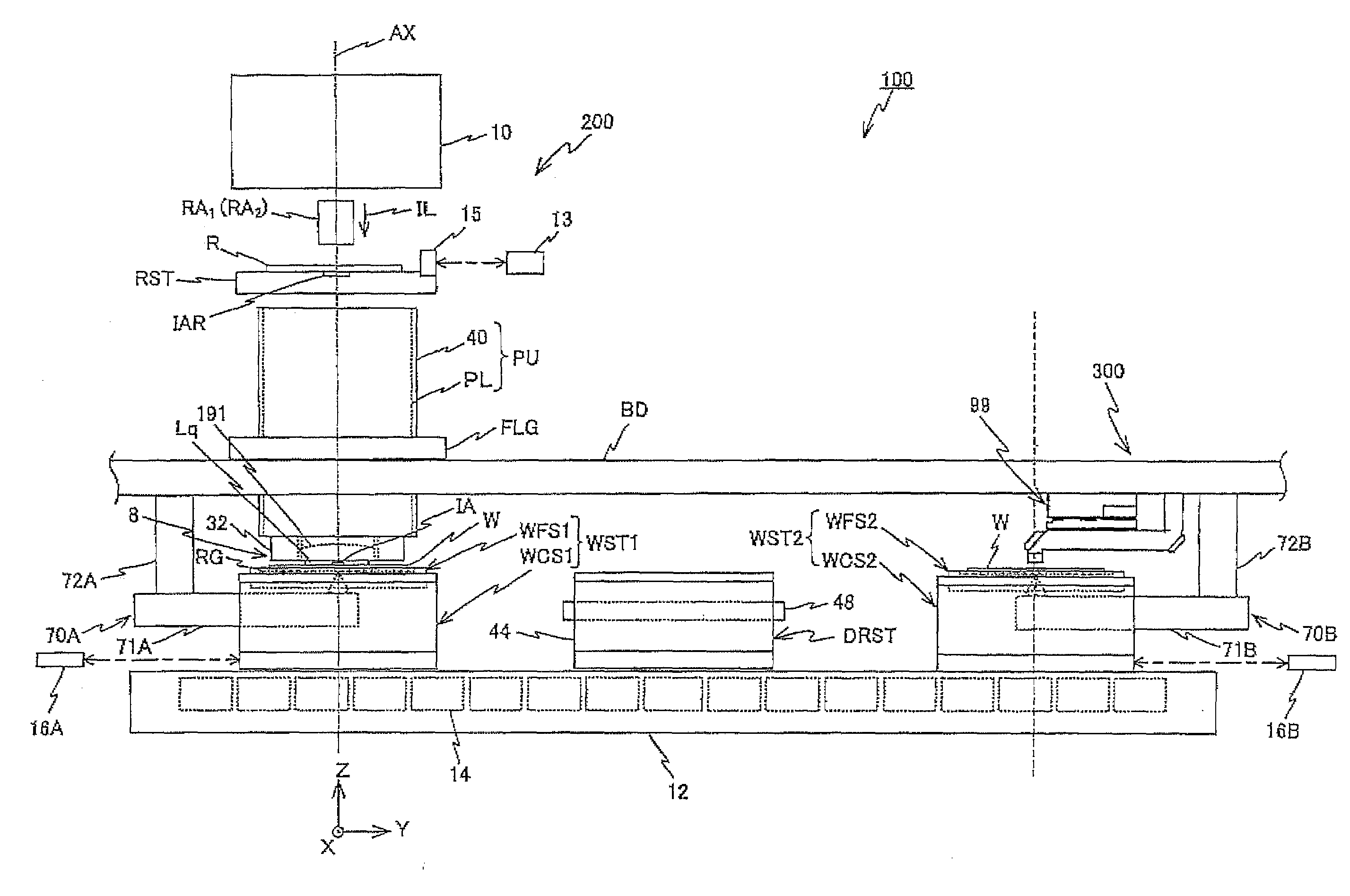
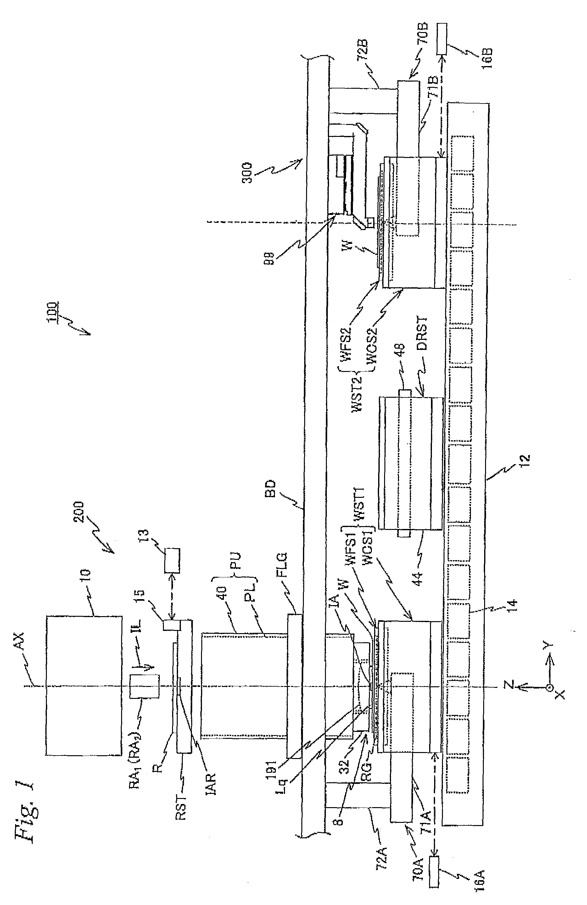
[0253]FIG. 33 shows a planar view of a measurement station 300 and a wafer exchange area (including an unloading position UP and a loading position LP) located on the +Y side of measurement station 300 of an exposure apparatus related to a modified example. As it can be seen from FIG. 33, on the +X side and the −X side of the wafer exchange area in a placement symmetric to a reference axis LV, an unloading position UP where a wafer is unloaded from fine movement stage WFS1 (or WFS2) and a loading position LP where a wafer is loaded on fine movement stage WFS1 (or WFS2) are placed, respectively.

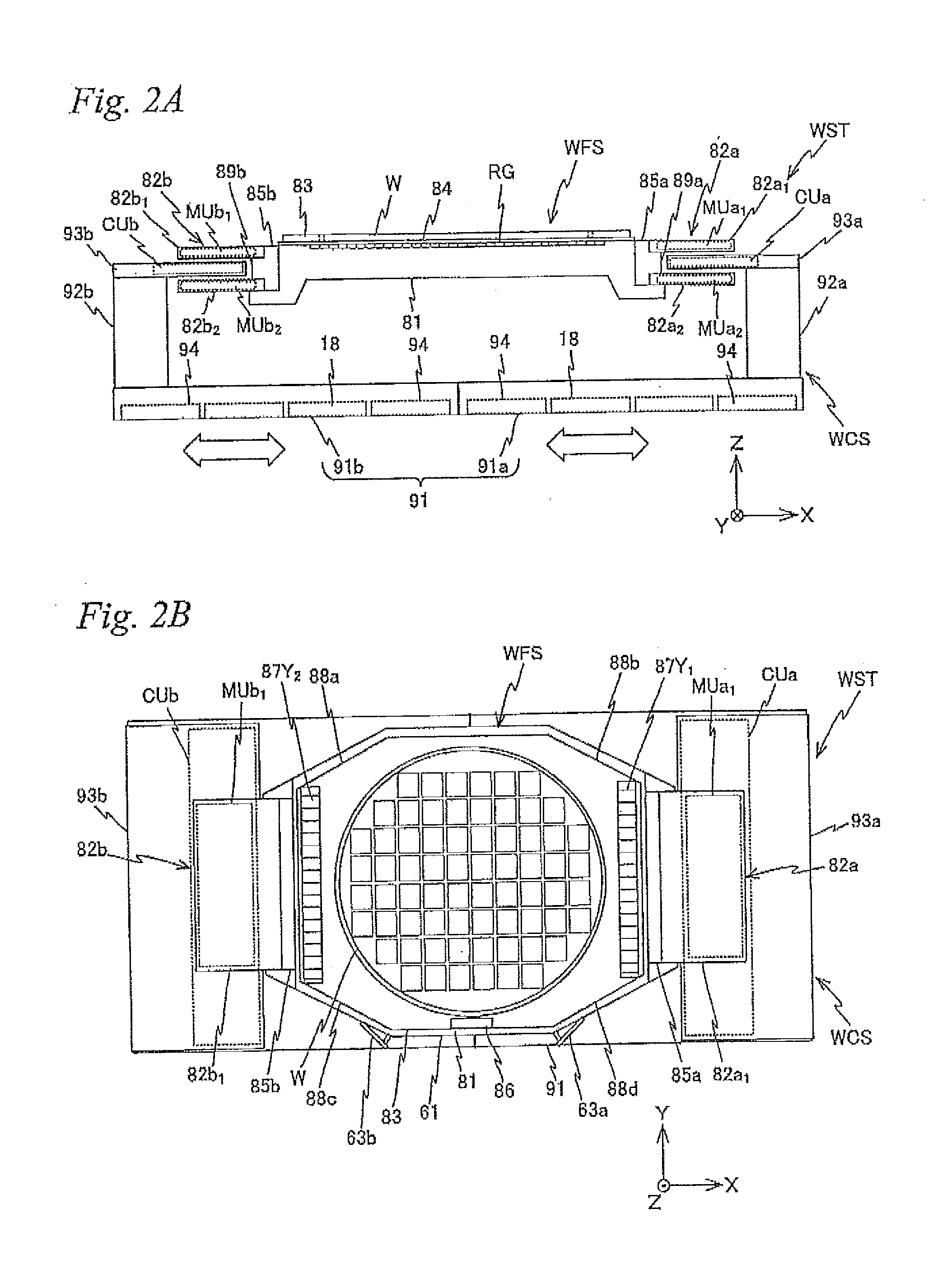
[0254]On fine movement stage WFS1 (or WFS2), grating RG is formed substantially covering the entire area of the upper surface of main body section 81.

[0255]Between measurement station 300, and unloading position UP and loading position LP, a head unit 98C is installed, which is equipped in another encoder system (hereinafter referred to as a third encoder system) different from encoder systems...


PUM

PropertyMeasurementUnit
Timeaaaaaaaaaa
Lengthaaaaaaaaaa
Areaaaaaaaaaaa

Abstract

In an exposure station, positional information of a stage holding a wafer is measured by a first fine movement stage position measurement system including a measurement arm, and in a measurement station, positional information of a stage holding a wafer is measured by a second fine movement stage position measurement system including another measurement arm. An exposure apparatus has a third fine movement stage position measurement system which can measure positional information of a stage when the stage is carried from the measurement station to the exposure station. The third fine movement stage measurement system includes an encoder system including a plurality of Y heads and a laser interferometer system including a laser interferometer.

Description

CROSS-REFERENCE TO RELATED APPLICATIONS[0001]This non-provisional application claims the benefit of Provisional Application No. 61 / 139,104 filed Dec. 19, 2008, and Provisional Application No. 61 / 213,375 filed Jun. 2, 2009, the disclosures of which are hereby incorporated herein by reference in its entirety.BACKGROUND OF THE INVENTION[0002]1. Field of the Invention[0003]The present invention relates to movable body apparatuses, exposure apparatuses, exposure methods, and device manufacturing methods, and more particularly, to a movable body apparatus including a movable body which can move along a plane parallel to a predetermined two-dimensional plane, an exposure apparatus which is equipped with the movable body apparatus and exposes an object with an energy beam, an exposure method performed in the exposure apparatus, and a device manufacturing method using the exposure apparatus or the exposure method.[0004]2. Description of the Background Art[0005]Conventionally, in a lithograph...

Claims


Application Information

Patent Timeline
IPC IPC(8): G03B27/58G01B9/02G01B11/14G03F7/20G05D3/12
CPCG03F7/70716G03F7/70733G03F7/708G03F7/70341G03F7/70775Y10T29/49826G03F7/00G03F7/20H01L21/027G01B11/002G03F7/7055
Inventor SHIBAZAKI, YUICHI
Owner NIKON CORP
Why Eureka
Try Eureka