Surgical sutures having collapsible tissue anchoring protrusions and methods therefor

a technology of surgical sutures and protruding protruding tissue, which is applied in the field of surgical sutures, can solve the problems and re-opening the wound or incision. , to achieve the effect of reducing the ability of the protruding tissue to fold and facilitating insertion

Active Publication Date: 2010-06-24
ETHICON INC
View PDF16 Cites 80 Cited by
  • Summary
  • Abstract
  • Description
  • Claims
  • Application Information

AI Technical Summary

Benefits of technology

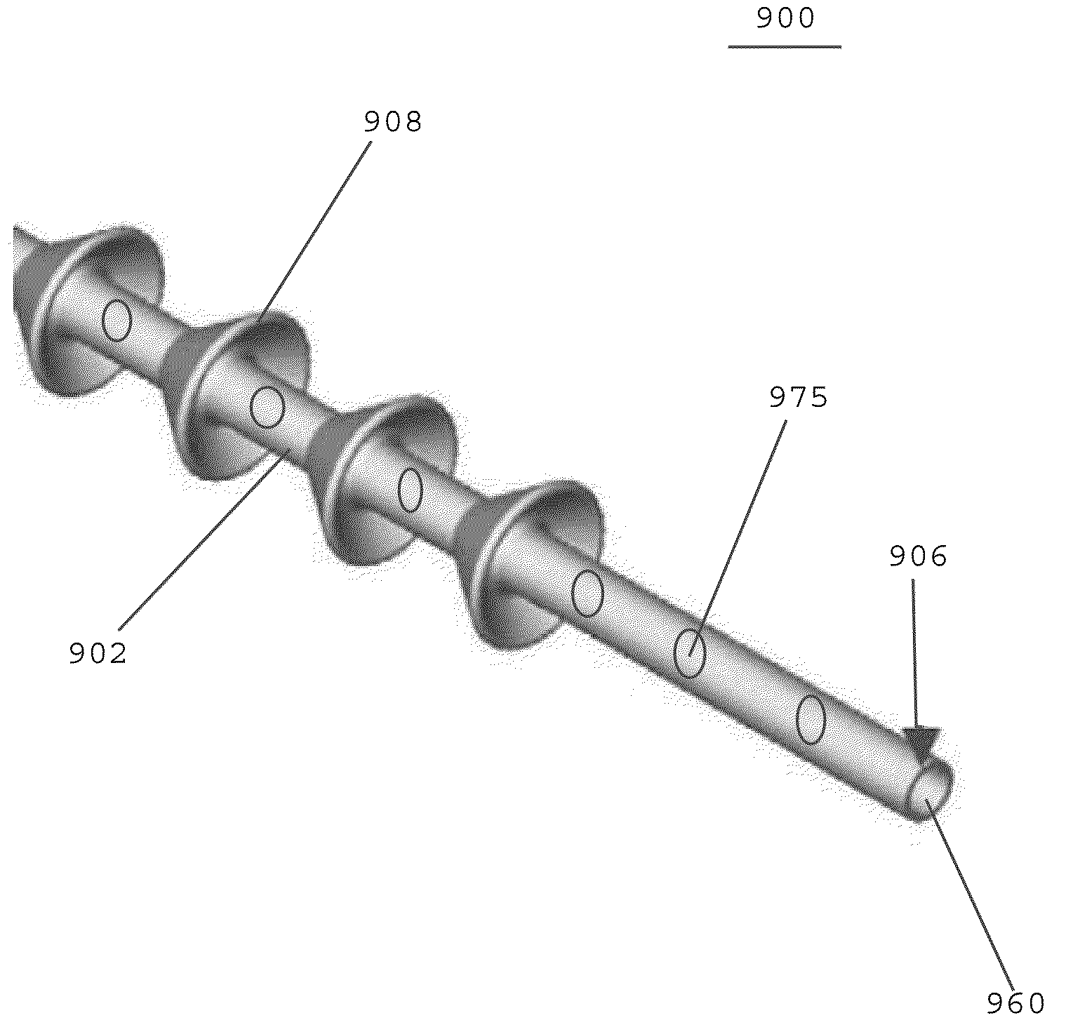
[0012]In one embodiment, a surgical suture includes a shaft having a length and an outer surface extending along the length of the shaft. The surgical suture desirably includes collapsible tissue anchoring protrusions extending from the outer surface of the shaft. In one embodiment, the flexible protrusions are similar to an umbrella whereby the device is passed through the tissue during installation and provide ease of insertion. After insertion, the flexible protrusions act to engage tissue and prevent device reversal from soft tissue through direct interference. This directional interference, coupled with the application geometry, serves to provide the means to approximate and secure wounds, or attach prosthetic devic

Problems solved by technology

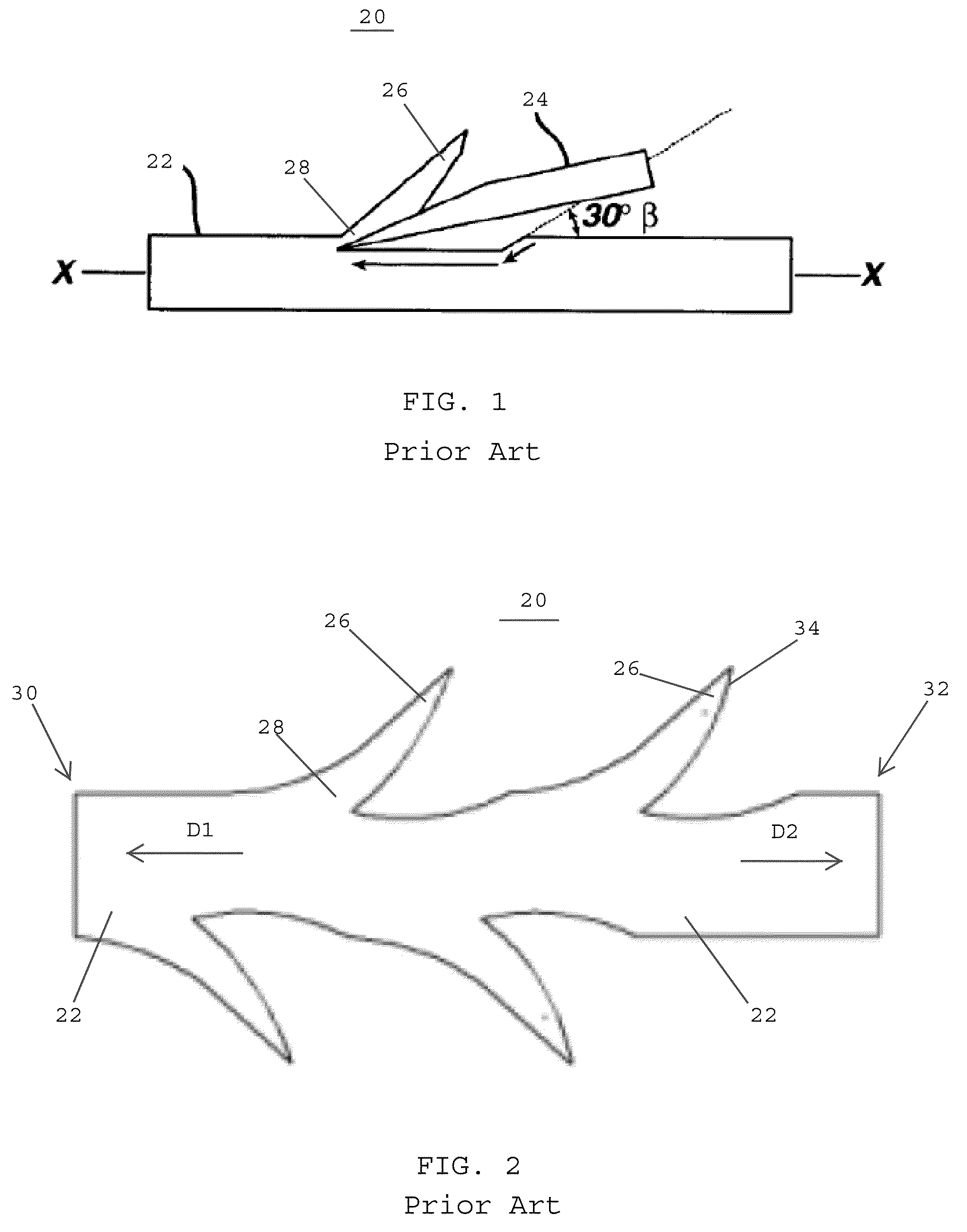
Although conventional surgical sutures are very effective for closing wounds and incisions, there are a number of problems associated with these sutures.
Many of these problems are directly related to the knots used to secure sutures in place.
If the knots are not tied properly, defects may arise including slippage, knot breakage, and re-opening of the wound or incision.
In addition, using knots to secure sutures may distort tissue, restrict blood flow, increase scar formation, impede wound healing, and result in infection.
In applications where a significant or pulsatile load is placed on the barbed suture, i.e., heart valve repair or replacement procedures and orthopedic applications, a given barb may fail, or beg

Method used


Image

  • Surgical sutures having collapsible tissue anchoring protrusions and methods therefor
  • Surgical sutures having collapsible tissue anchoring protrusions and methods therefor
  • Surgical sutures having collapsible tissue anchoring protrusions and methods therefor

Examples


Embodiment Construction

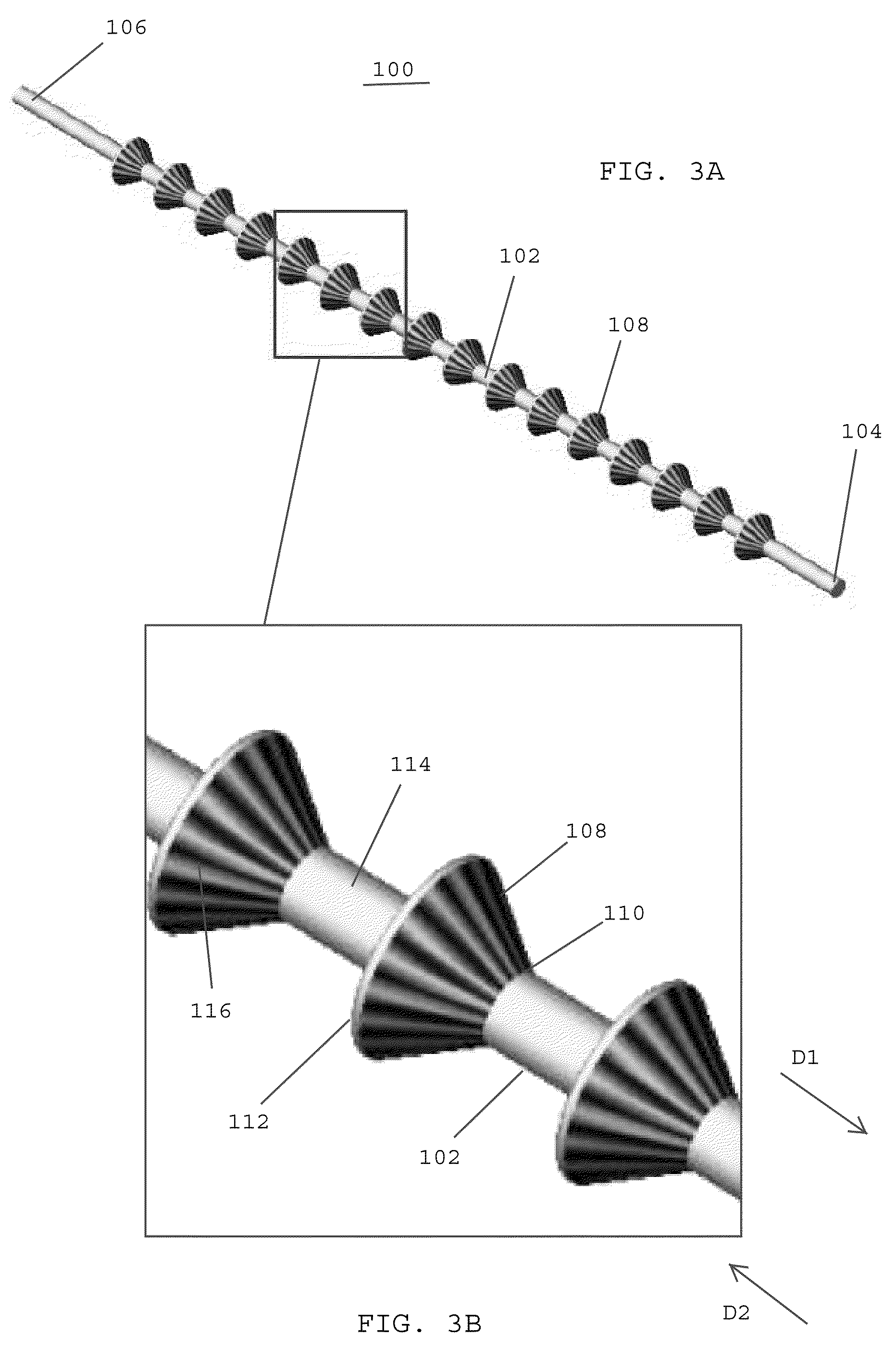
[0046]Referring to FIG. 3A, in one embodiment, a surgical suture 100 includes an elongated shaft 102 having a leading end 104 and a trailing 106. The elongated shaft is desirably flexible so that the shaft may flex and bend as the surgical suture 100 passes through tissue and / or prosthetic components. The surgical suture desirably includes a plurality of flexible protrusions 108 that extend outwardly from the elongated shaft 102. The flexible protrusions are adapted to collapse inwardly toward the shaft as the leading end 104 of the suture is pulled through tissue or a prosthetic device.

[0047]Referring to FIG. 3B, in one embodiment, each of the flexible protrusions 108 includes a base 110 adjacent the shaft 102 and a flared ring 112 that is spaced from the outer surface 114 of the shaft 102. In one embodiment, the diameter of the flared ring 112 is larger than the diameter of the base section 110.

[0048]In one embodiment, each of the flexible protrusions 108 has one or more weakened ...


PUM


Abstract

A surgical suture includes a shaft having a leading end, a trailing end, and an outer surface extending between the leading and trailing ends. The surgical suture includes a plurality of flexible protrusions extending from the shaft, and a lumen extending between the leading and trailing ends of the shaft. The shaft includes a plurality of openings formed in the outer surface thereof that are in communication with the lumen. The shaft includes a first axial opening at the leading end thereof in communication with the lumen and a second axial opening at the trailing end thereof in communication with the lumen. A flowable material may be disposed in the lumen. After the surgical suture is implanted, the flowable material is adapted to pass from the lumen and through the plurality of openings in the outer surface of the shaft for contacting tissue surrounding the suture.

Description

BACKGROUND OF THE INVENTION[0001]1. Field of the Invention[0002]The present invention generally relates to surgical sutures, and more specifically relates to surgical sutures having collapsible tissue anchoring protrusions for closing wounds and anchoring the surgical sutures in tissue and / or prosthetic devices.[0003]2. Description of the Related Art[0004]Surgical sutures are used for closing wounds and surgical incisions, and repairing damaged muscles, vessels, and tissue. Typically, a needle is attached to one end of the suture, and the needle is drawn through tissue to form one or more loops holding the tissue together. The suture is subsequently tied off in one or more knots so that the tissue will remain drawn together, or so that a prosthetic device will remain anchored in place.[0005]Although conventional surgical sutures are very effective for closing wounds and incisions, there are a number of problems associated with these sutures. Many of these problems are directly relat...

Claims


Application Information

Patent Timeline
IPC IPC(8): A61B17/04
CPCA61B17/06166A61B2017/00004A61B2017/00526A61B2017/06185A61B2017/00951A61B2017/06176A61B2017/00893
Inventor NAWROCKI, JESSE G.LINDH, SR., DAVID C.ROUSSEAU, ROBERT A.
Owner ETHICON INC
Why Eureka
Try Eureka