Robot joint driving apparatus and robot having the same

a technology of robots and driving apparatuses, applied in the direction of joints, gearing, program-controlled manipulators, etc., can solve the problems of low driving efficiency and ineffective robot-human interaction

Active Publication Date: 2010-07-01
SAMSUNG ELECTRONICS CO LTD
View PDF7 Cites 30 Cited by
  • Summary
  • Abstract
  • Description
  • Claims
  • Application Information

AI Technical Summary

Benefits of technology

[0019]The guide part allows the movable member to linearly and slidably move. The coupling member is formed with a w

Problems solved by technology

The joint driving scheme using the reduction unit is limited as to the arrangement of the driving apparatus, which causes severe noise in operation and results in

Method used


Image

  • Robot joint driving apparatus and robot having the same
  • Robot joint driving apparatus and robot having the same
  • Robot joint driving apparatus and robot having the same

Examples


first embodiment

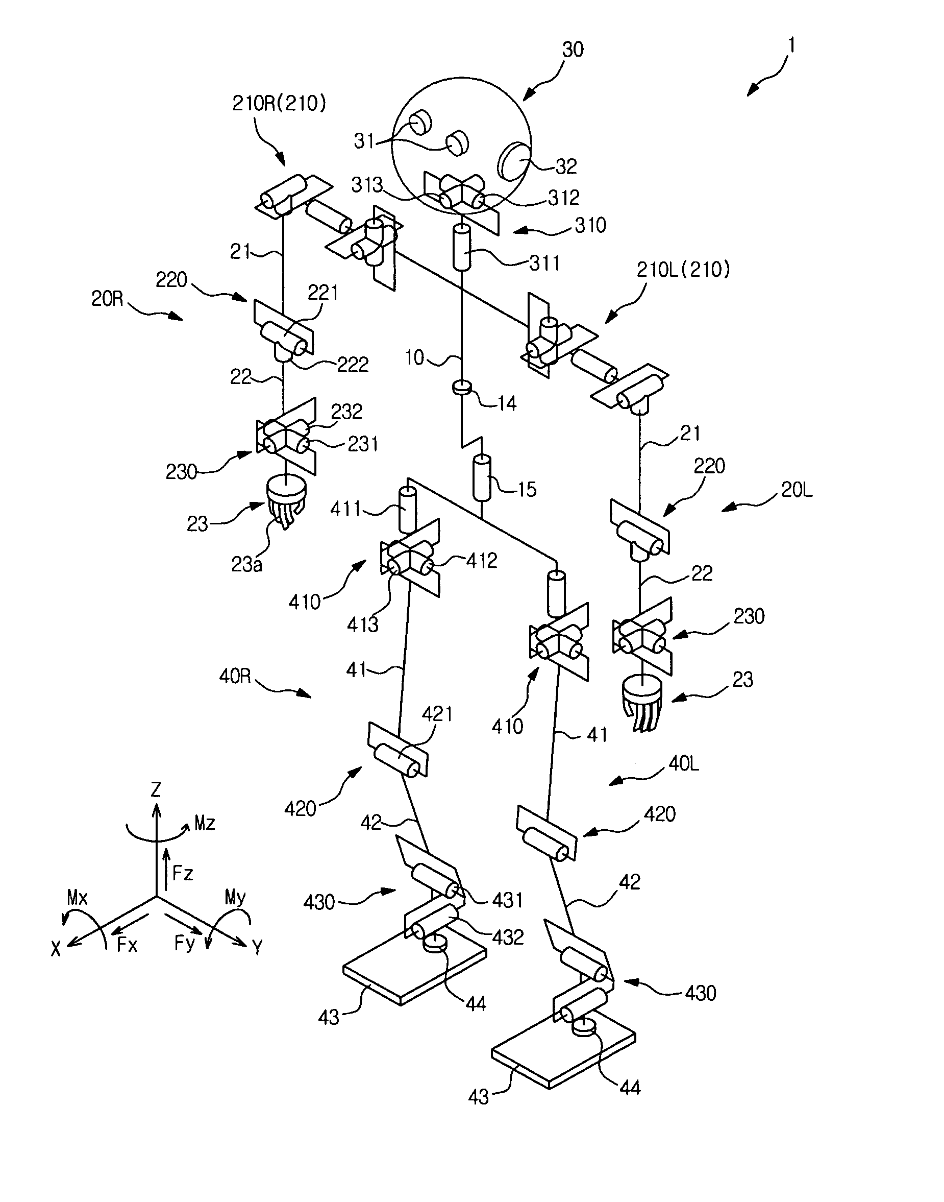
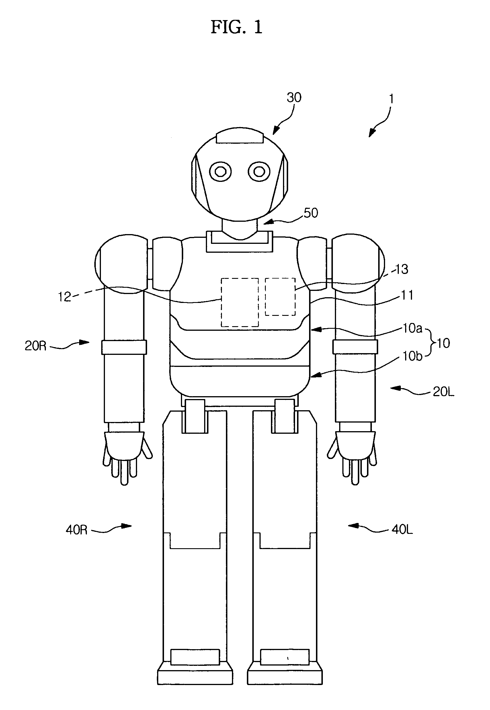
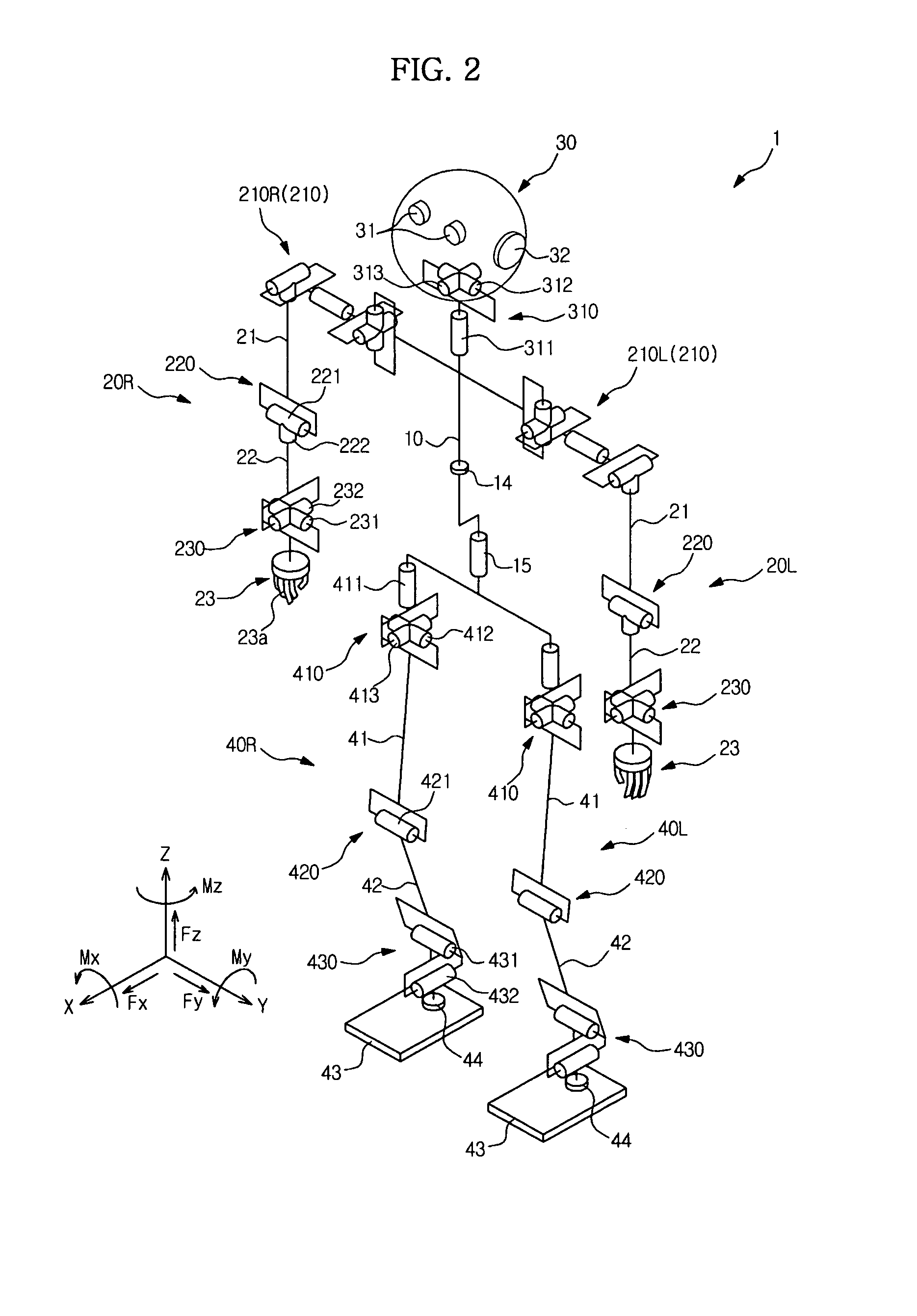
[0041]FIG. 1 is a view showing an external appearance of a humanoid robot according to the present invention, and FIG. 2 is a view schematically showing a structure of the humanoid robot shown in FIG. 1.

[0042]As shown in FIGS. 1 and 2, a humanoid robot (hereinafter, simply referred to as a ‘robot’) 1 includes a central body 10, arms 20R and 20L connected to both upper sides of the central body 10, a head 30 connected to an upper end of the central body 10, and legs 40R and 40L connected to both lower sides of the central body 10. The arms 20R and 20L are connected to the central body 10 through shoulder joint assemblies 210R and 210L, and the head 30 is connected to the central body 10 through a neck 50. Reference numerals “R” and “L” represent a right side and a left side, respectively.

[0043]The interior of the central body 10 is protected by a cover 11. A control unit 12, a battery 13 and an inclination sensor 14 (see, FIG. 2) are installed in the central body 10. The inclination ...

second embodiment

[0087]Hereinafter, a joint driving apparatus according to the present invention and a robot having the same will be described.

[0088]FIG. 8 is a perspective view showing a part of the knee joint driving apparatus according to the second embodiment of the present invention. In the joint driving apparatus according to the second embodiment, the same reference numerals will be assigned to the same elements of the first embodiment and detailed description thereof will be omitted in order to redundancy.

[0089]A joint driving apparatus 500′ according to the second embodiment of the present invention includes the reversible drive motor 510, a pair of movable members 533 and 543, which perform a linear movement according to rotation of the drive motor 510, the wire 550 connected to the movable members 533 and 543, an idle pulley assembly 560′ rotatably installed at one end of the wire 550, the knee joint part 420 rotatably installed at the opposite end of the wire 550, a load cell 570 detecti...

third embodiment

[0091]Hereinafter, a joint driving apparatus according to the present invention and a robot having the same will be described.

[0092]FIG. 9 is a perspective view showing a part of a knee driving apparatus according to the third embodiment of the present invention. In the joint driving apparatus according to the third embodiment, the same reference numerals will be assigned to the same elements of the first embodiment and detailed description thereof will be omitted in order to avoid redundancy.

[0093]As shown in FIG. 9, a ball screw apparatus 520′ according to the third embodiment of the present invention includes a guide bar 540′ disposed in parallel to the first ball screw part 530.

[0094]The guide part 540′ is disposed in parallel to the first ball screw part 530 such that driving force is not transferred to the second movable member 543 and the first and second movable members 533 and 543 perform an up / down linear movement without rotation. That is, the guide bar 540′ allows the fi...


PUM


Abstract

Disclosed are a robot joint driving apparatus and a robot having the same, capable of minimizing tension of a wire applied to a movable member by installing an idle pulley in a power transmission structure using a ball screw apparatus and the wire. The robot joint driving apparatus includes a reversible drive motor, a pair of movable members performing a linear movement according to rotation of the reversible drive motor, a wire connected to the movable members from both directions of the movable members, an idle pulley rotatably installed at one side of the wire, a joint part rotatably installed at an opposite side of the wire, and an adjustment unit to adjust tension of the wire.

Description

CROSS-REFERENCE TO RELATED APPLICATIONS[0001]This application claims the benefit of Korean Patent Application No. 10-2008-0135457, filed on Dec. 29, 2008, in the Korean Intellectual Property Office, the disclosure of which is incorporated herein by reference.BACKGROUND[0002]1. Field[0003]The present invention relates to a robot joint driving apparatus and a robot having the same. More particularly, the present invention relates to a robot joint driving apparatus provided with an improved joint driving structure and a robot having the same.[0004]2. Description of the Related Art[0005]Recently, various robots such as biped walking robots and quadruped walking robots have been developed for household, industrial and military use.[0006]These robots perform various actions in addition to running and walking, which is achieved with joints. The joints can be driven by using a motor and a reduction unit connected to the motor or by using a wire.[0007]The joint driving scheme using the reduc...

Claims


Application Information

Patent Timeline
IPC IPC(8): B25J18/00
CPCB25J9/1045Y10T74/20323Y10T74/20329Y10T74/18832
Inventor LEE, YOUN BAEKSIM, HYUN SIKYANG, SOO SANG
Owner SAMSUNG ELECTRONICS CO LTD
Why Eureka
Try Eureka