Throttle grip apparatus

Active Publication Date: 2010-07-01
ASAHI DENSO KABUSHIKI KAISHA
View PDF6 Cites 10 Cited by
  • Summary
  • Abstract
  • Description
  • Claims
  • Application Information

AI Technical Summary

Benefits of technology

[0010]One or more embodiments of the invention provide a throttle grip apparatus which, in spite of omission of a throttle wire, allows a driver to operate a throttle grip without feeling uncomfortable and also can be reduced in size.
[0012]According to the above structure, since the frictional plate, when the throttle grip is rotated, capable of generating resistance to thereby generate the rotation load of the throttle grip is disposed within the handle bar, even when a throttle wire is omitted, the throttle grip can be operated with no uncomfortable feeling.
[0014]According to the above structure, by the resistance adjustor capable of arbitrarily adjusting the resistance generated by the frictional plate, the rotation load of the throttle grip can be arbitrarily changed according to the taste of a driver and, even when the throttle wire is omitted, the driver is allowed to operate the throttle grip without feeling uncomfortable.
[0016]According to the above structure, the frictional plate includes a rotation side frictional plate rotatable together with the throttle grip and a fixed side frictional plate fixed to the interior of the handle bar and contacted with the rotation side frictional plate, and the resistance adjustor includes an urging member for pressing the rotation side frictional plate against the fixed side frictional plate and an adjusting mechanism capable of arbitrarily changing the urging force of the urging member from outside. Therefore, by operating the adjusting mechanism, the pressing force of the rotation side frictional plate against the fixed side frictional plate can be adjusted. This structure makes it possible to adjust more easily the resistance generated by the frictional plate.
[0019]According to the above structure, since the adjusting mechanism includes a tool fit-shape portion facing the leading end of the throttle grip and, when a tool is fitted with the tool fit-shape portion and the adjusting mechanism is rotated, the urging force of the urging member can be changed arbitrarily, the frictional generated by the frictional plate can be adjusted still more easily.

Problems solved by technology

Therefore, as a force to be transmitted to the driver side when the throttle grip is rotated, there can be provided only a force of a return spring that returns the throttle grip to its initial position, which causes the driver to feel uncomfortable.
However, in the conventional throttle grip apparatus including the above frictional plate, since the friction plate is disposed in the case fixed at the position adjacent to the throttle grip, although the rotation load of the throttle grip can be obtained when the throttle grip is rotated, there is raised a problem that the throttle grip apparatus itself increases in size.

Method used


Image

  • Throttle grip apparatus
  • Throttle grip apparatus
  • Throttle grip apparatus

Examples


first exemplary embodiment

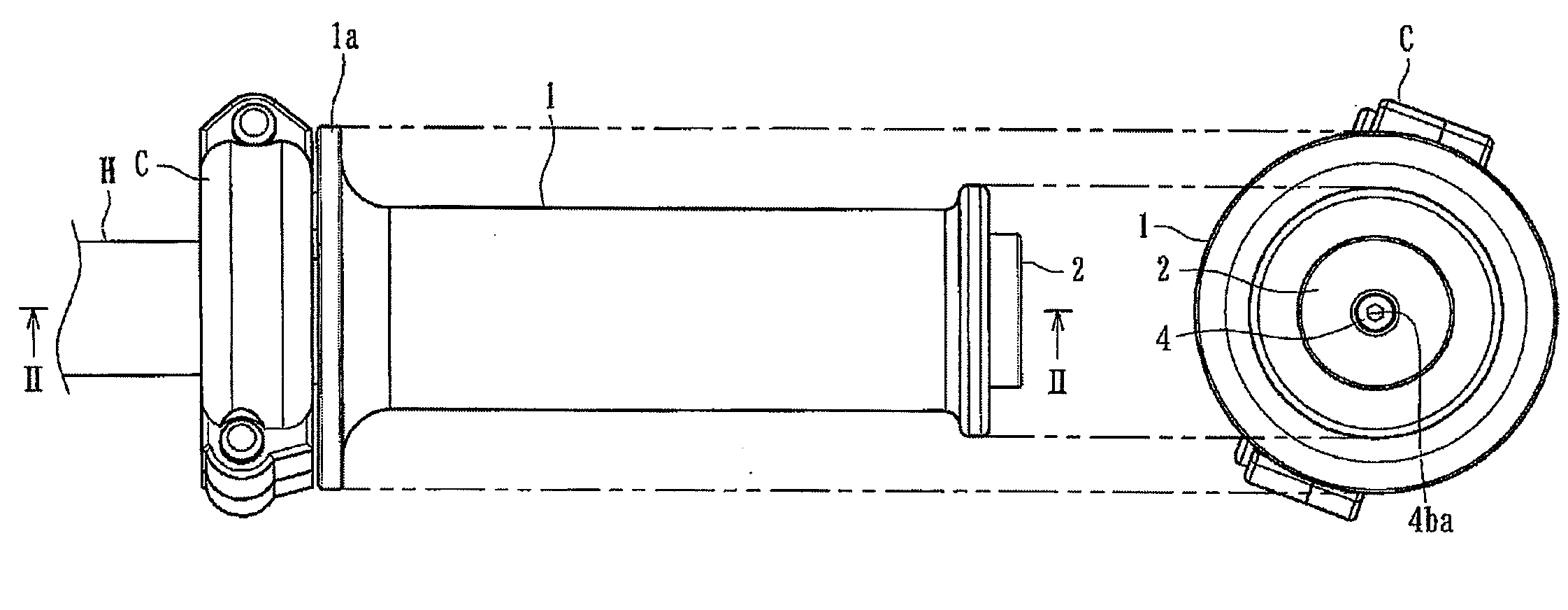
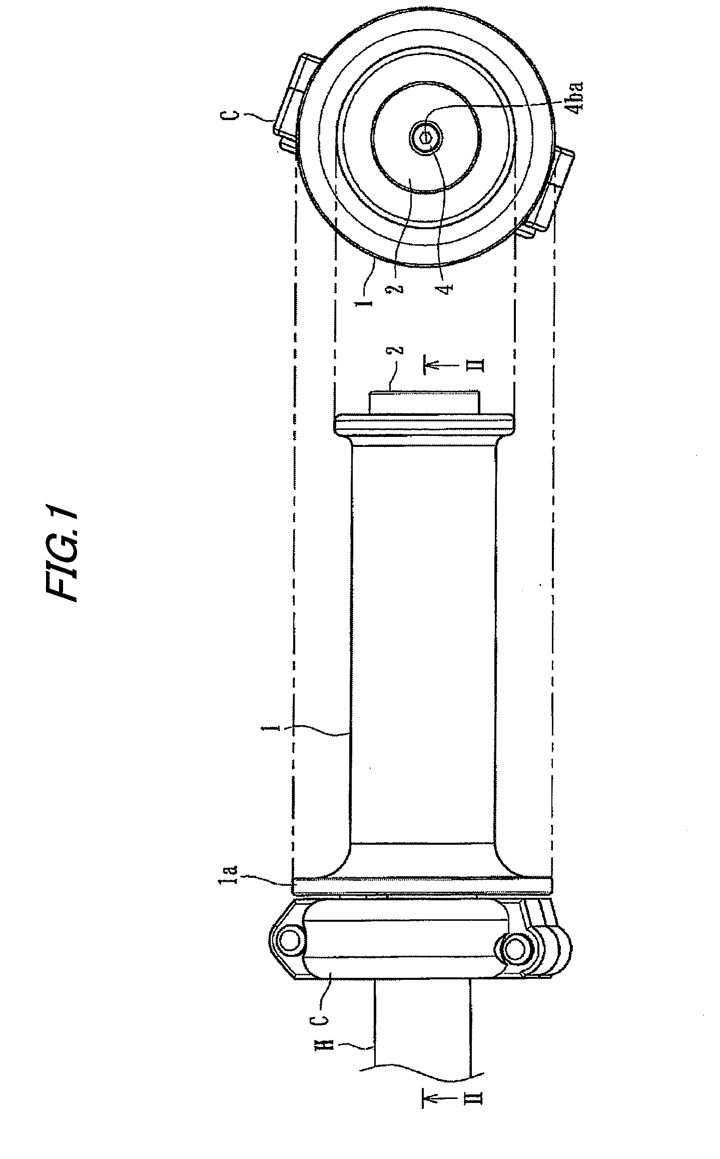
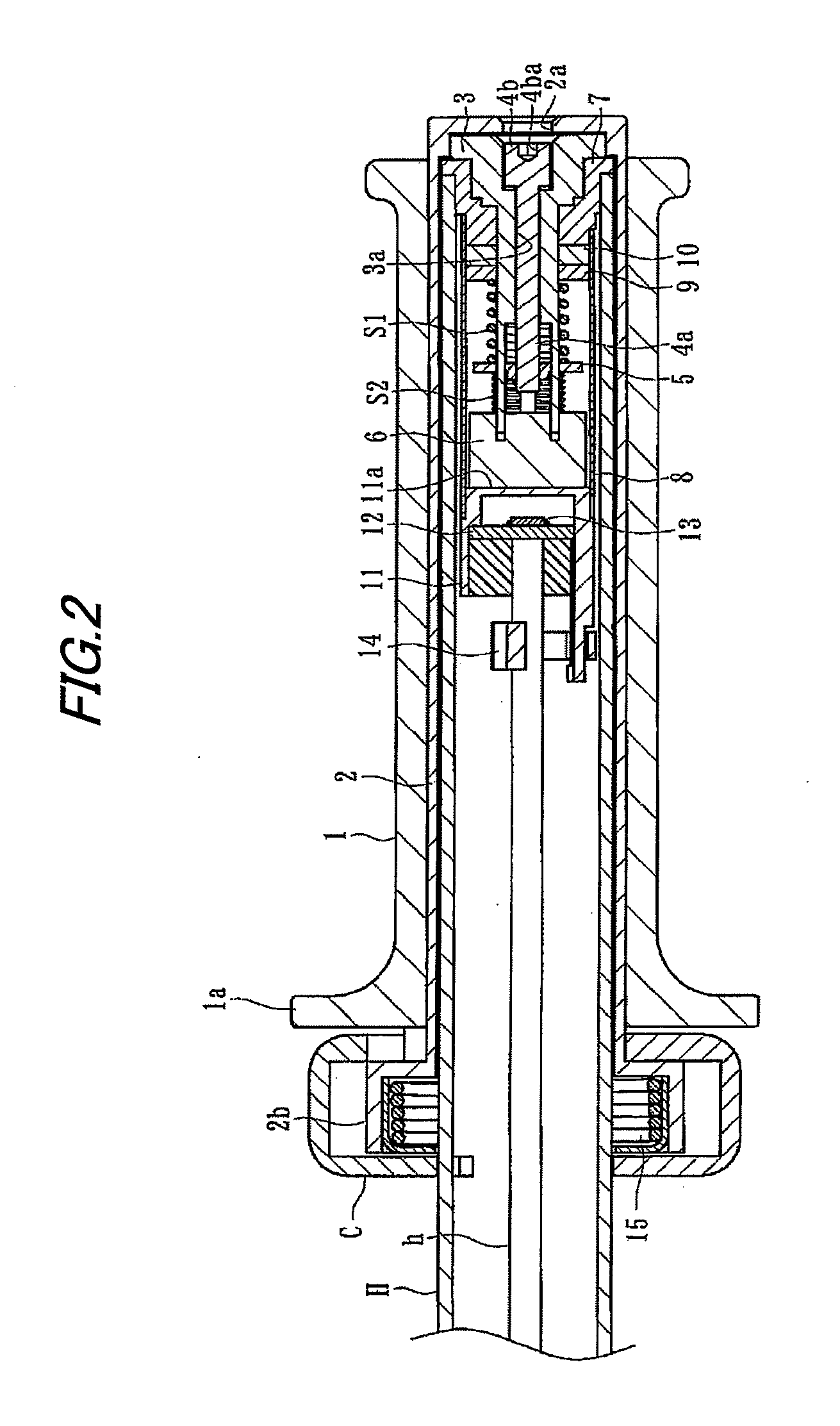
[0028]A throttle grip apparatus according to a first embodiment of the invention is used to detect a rotation angle of a throttle grip mounted on a handle bar of a motorcycle and also to transmit a detected signal to an electronic control unit such as ECU mounted in the motorcycle. As shown in FIGS. 1 to 4, the handle grip apparatus includes, as its main composing elements, a throttle grip 1, a magnet 6, an angle sensor 13 serving as a detector, a rotation side frictional plate 9 and a fixed side frictional plate 10 respectively disposed within a handle bar H, and an energizing member S1 and an adjusting mechanism (a bolt member 4 and an adjusting member 5) cooperating together in constituting a resistance adjustor.

[0029]The throttle grip 1 is mounted on a leading end portion of the handlebar H of the motorcycle and can be rotated relative to the handle bar H coaxially therewith. An outer peripheral surface of the throttle grip 1 provides a grip portion which can be gripped by a dri...

second exemplary embodiment

[0046]Description will be given below of a second embodiment of a throttle grip apparatus according to the invention.

[0047]A throttle grip apparatus according to the present embodiment, similarly to the first embodiment, is used to detect the rotation angle of a throttle grip mounted on a handlebar of a motorcycle and to transmit the thus detected signal to an electronic control unit such as ECU mounted in the motorcycle.

[0048]As shown in FIGS. 5 and 6, the present handle grip apparatus includes, as its main composing elements, a throttle grip 1, a magnet 6, an angle sensor 13, a rotation side frictional plate 9 and a fixed side frictional plate 10 respectively disposed within a handle bar H, and an energizing member S1 and an adjusting mechanism (a bolt member 4 and an adjusting member 5) cooperating together in constituting a resistance adjusting unit. Here, the composing elements of the present embodiment similar to those of the first embodiment are given the same designations an...


PUM


Abstract

A throttle grip apparatus is provided with: a throttle grip (1) rotatably mounted on a leading end of a handle bar (H) of a vehicle; a magnet (6) rotatable together with the throttle grip (1); a detector (13) for detecting variations in a magnetic field of the magnet (6) in a non-contact manner to detect a rotation angle of the throttle grip (1); and a frictional plate (9, 10) for generating a rotation load of the throttle grip (1). An engine of the vehicle is controlled based on a detected value of the detector (13). The frictional plate (9, 10) is disposed within the handle bar (H).

Description

BACKGROUND OF THE INVENTION[0001]1. Field of the Invention[0002]The present invention relates to a throttle grip apparatus for controlling an engine of a vehicle according to a rotation angle of a throttle grip.[0003]2. Background Art[0004]Recently, there has been spread a motorcycle of a type that, a rotation angle of a throttle grip is detected using a throttle opening angle sensor such as a potentiometer and the thus detected value of the rotation angle is sent as an electric signal to an electronic control unit or the like incorporated in the motorcycle. The electronic control unit carries out a given operation according to such detection signal, and an ignition timing of the engine or an opening / closing of an exhaust valve can be controlled according to results of such operation.[0005]For example, in the patent reference 1 (JP-A-04-254278), there is disclosed a throttle grip apparatus having the above-mentioned structure. Such throttle grip apparatus includes mainly a drive pul...

Claims


Application Information

Patent Timeline
IPC IPC(8): B62K23/04G05G1/08
CPCB62K23/04F02D11/02F02D11/106Y10T74/20474
Inventor SUZUKI, MICHIYUKI
Owner ASAHI DENSO KABUSHIKI KAISHA
Why Eureka
Try Eureka