
Reflux Trap Device

a trap device and trap technology, applied in the field of traps, can solve the problems of contaminated components, flow back into the plasma generator system, etc., and achieve the effect of preventing the backflow of fluids and debris

Active Publication Date: 2010-07-01
BOVIE MEDICAL CORPORATION
View PDF20 Cites 3 Cited by
  • Summary
  • Abstract
  • Description
  • Claims
  • Application Information

AI Technical Summary

Benefits of technology

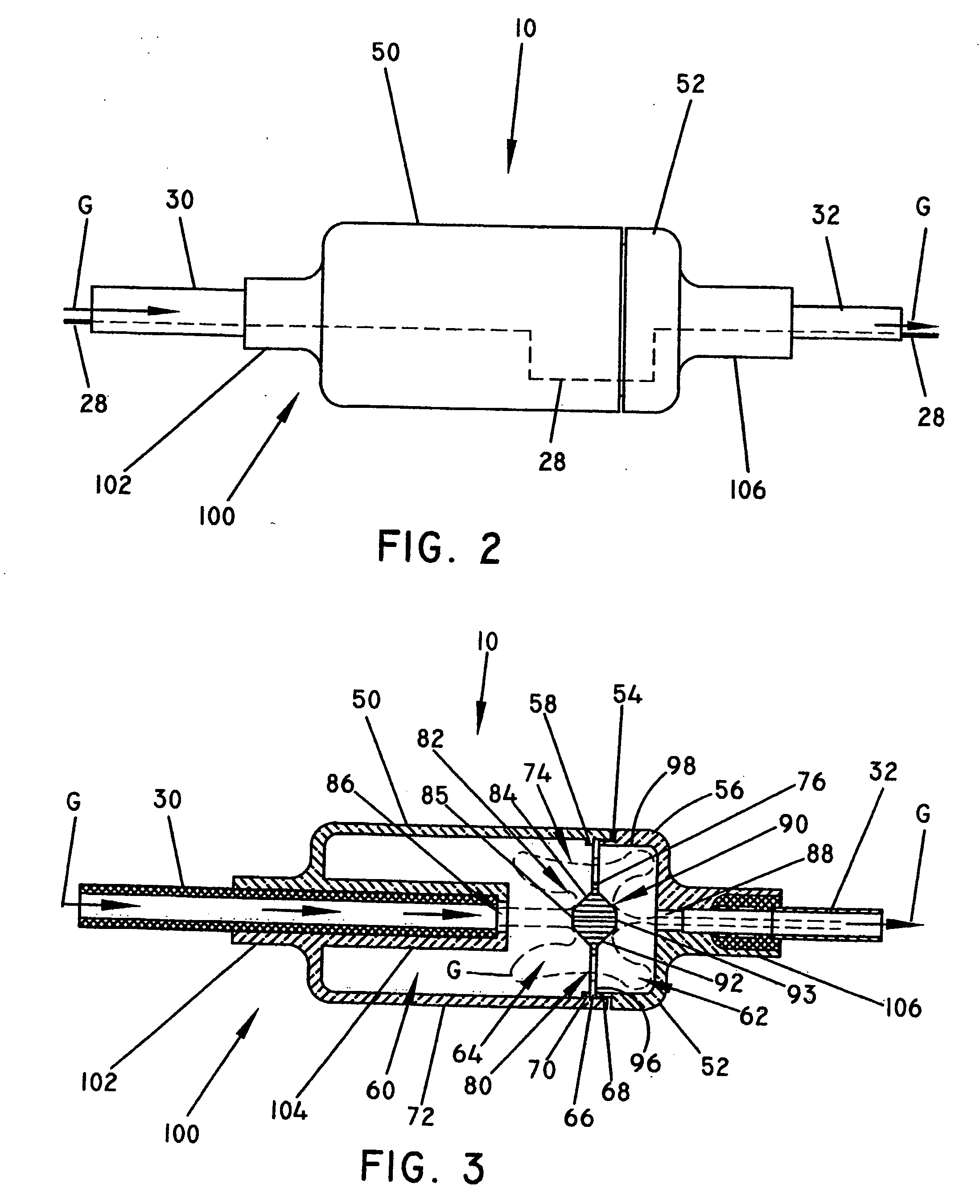
The present invention is about a device called a reflux trap that prevents fluids and debris from a patient from flowing back into a plasma generator during a surgical procedure. The reflux trap is connected to the gas feed conduit that supplies inert gas to the surgical probe. It has a housing with two chambers separated by a baffle. The baffle has a gas flow aperture and a diffuser member that directs the inert gas from the source to the surgical site on the patient. The reflux trap also has a deflection member that deflects backflowing fluids and debris to a collection area between the baffle and the deflection chamber. This prevents the contamination of the plasma generator and ensures safe and effective surgical procedures.

Problems solved by technology

A disadvantage of common to plasma generators resides in the fact that during insertion of the probe into the body cavity or after a probe has already been inserted the inert gas, as well as fluids and / or debris from the patient may flow back into the plasma generator system.
As a result, various components may become contaminated.

Method used


Image

  • Reflux Trap Device
  • Reflux Trap Device
  • Reflux Trap Device

Examples


Embodiment Construction

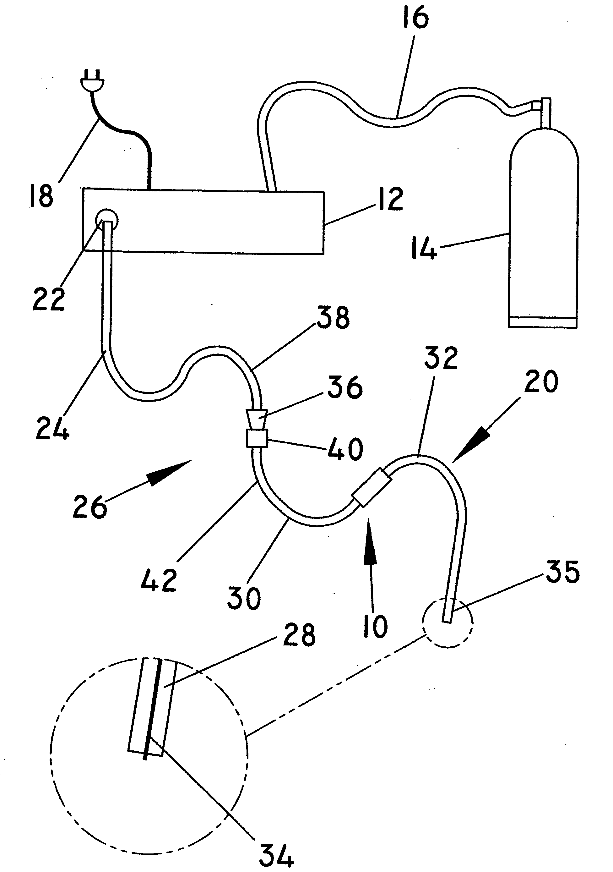
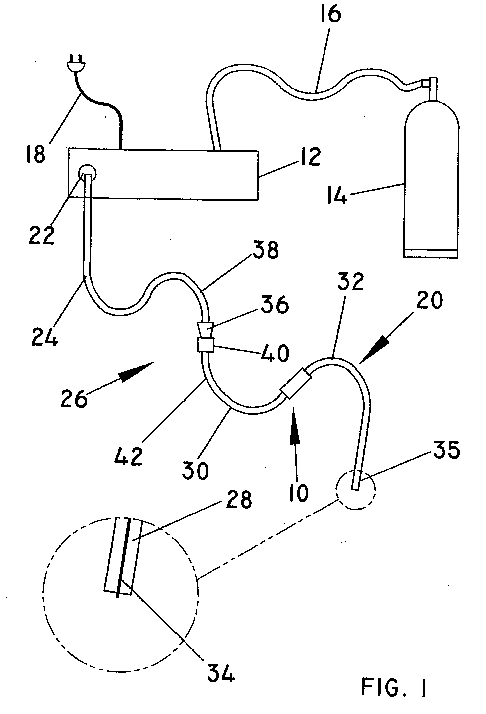
[0027]As shown in FIG. 1, the present invention relates to a reflux trap generally indicated as 10 for use in a plasma generator and delivery system to prevent back flow of fluids and debris from a patient to the plasma generator.

[0028]The plasma generator and delivery system comprise an electrosurgical generator 12 coupled to an inert gas source such as argon 14 by a gas supply conduit 16 and to an external power source (not shown) by a conductor 18 and a surgical probe generally indicated as 20 coupled to the output 22 of the electrosurgical generator 12 by a proximal gas feed conduit 24 and a connector generally indicated as 26.

[0029]The surgical probe 20 comprises an electrode 28 disposed within a distal gas feed conduit including a first distal gas feed conduit section 30 and a second distal gas feed conduit section 32 terminating in an ingiter tip 34 disposed at the distal portion 35 of the surgical probe 20 to receive radio frequency power from the electrosurgical generator 1...


PUM

PropertyMeasurementUnit
radio frequency poweraaaaaaaaaa
diameteraaaaaaaaaa
frequency electrical energyaaaaaaaaaa

Abstract

A reflux trap for use in a plasma generator and delivery system to prevent back flow of fluids and debris from a patient to the plasma generator during a surgical procedure comprising a trap housing including a proximal diffuser chamber and a distal deflection chamber having a collection area separated by a baffle disposed within the trap housing having at least one gas flow aperture formed therethrough, a proximal inlet port and a distal outlet port formed on opposite end portions of the trap housing to feed gas to and from the trap housing through the proximal diffuser chamber, gas flow aperture and the distal deflection chamber, the baffle further includes a diffuser member disposed in the proximal diffuser chamber such that gas fed into the proximal diffuser chamber through the proximal inlet port impigns thereon and diffused through the gas flow aperture into the distal deflection chamber and through the distal outlet port to the surgical site on the patient and a deflection member disposed in the distal deflection chamber such that fluids and debris flowing back from the patient through the outlet port into the distal deflection chamber impign thereon and are deflected away from the gas flow aperture to the collection area preventing fluids and debris from migrating through the gas flow aperture into the proximal diffuser chamber isolating the plasma generator against any back flow of fluid and debris from the patient.

Description

CROSS-REFERENCE[0001]This application claims priority based upon provisional application filed Dec. 5, 2008 for Inventor Gary Gerard Gogolin, entitled Reflux Trap Device.BACKGROUND OF THE INVENTION[0002]1. Field of the Invention[0003]A reflux trap for use in a plasma generator and delivery system to prevent back flow of fluids and debris from a patient to the plasma generator during a surgical procedure.[0004]2. Description of the Prior Art[0005]High frequency electrical energy has been widely used in surgery. Tissue is cut and bodily fluids are coagulated using electrosurgical energy.[0006]Electrosurgical instruments generally comprise “monopolar” devices or “bipolar” devices. Monopolar devices comprise an active electrode on the electrosurgical instrument with a return electrode attached to the patient. In monopolar electrosurgery, the electrosurgical energy flows through the active electrode on the instrument through the patient's body to the return electrode. Such monopolar devi...

Claims


Application Information

Patent Timeline
Patent Type & Authority Applications(United States)
IPC IPC(8): B03C3/38
CPCA61B18/042
Inventor GOGOLIN, GARY GERARD
Owner BOVIE MEDICAL CORPORATION
Learn More