
Injection member for manufacturing semiconductor device and plasma processing apparatus having the same

a technology of semiconductor devices and injection members, which is applied in the direction of plasma techniques, chemical vapor deposition coatings, coatings, etc., can solve the problems of delay in process time, difficult control of space between substrate and showerhead, and difficulty in forming thin films on the substrate, etc., and achieves high frequency power

Inactive Publication Date: 2013-10-24
KOOKJE ELECTRIC KOREA +1
View PDF8 Cites 73 Cited by
  • Summary
  • Abstract
  • Description
  • Claims
  • Application Information

AI Technical Summary

Benefits of technology

The patent describes an injection member for a plasma processing apparatus that can mount multiple substrates and generate stable plasma. The injection member has baffles that can control the space between the substrate and the plasma generating region. The apparatus includes a process chamber, a support member, an injection member, and a driving part. The injection member has baffles and a plasma generator for injecting reaction and purge gases. The apparatus can control the vertical position of the plasma generator to adjust the space between the substrate and the plasma generator. The injection member can have a level controller to adjust the space between the plasma generator and the substrate. The plasma generator has electrodes for turning gas into plasma and can have a comb-type or circular disk configuration. The injection member can have a nozzle part with multiple injection openings and a showerhead plate for separate injection of gases. The technical effects of the invention include stable plasma generation, improved substrate processing uniformity, and efficient gas utilization.

Problems solved by technology

Since conventional plasma processing apparatuses have a one-body type showerhead, it has been hard to control a space between the substrate and the showerhead.
Although conventional plasma processing apparatuses have a remote plasma generator, in the case that a plasma source is spaced far apart from a substrate, there is a technical difficulty in forming a thin film on the substrate.
For example, there may be a heavy loss of ionized gas, and this leads to a delay in process time and deterioration in quality of thin film.
As a result, the use of the conventional plasma processing apparatuses has been limited.

Method used


Image

  • Injection member for manufacturing semiconductor device and plasma processing apparatus having the same
  • Injection member for manufacturing semiconductor device and plasma processing apparatus having the same
  • Injection member for manufacturing semiconductor device and plasma processing apparatus having the same

Examples


embodiments

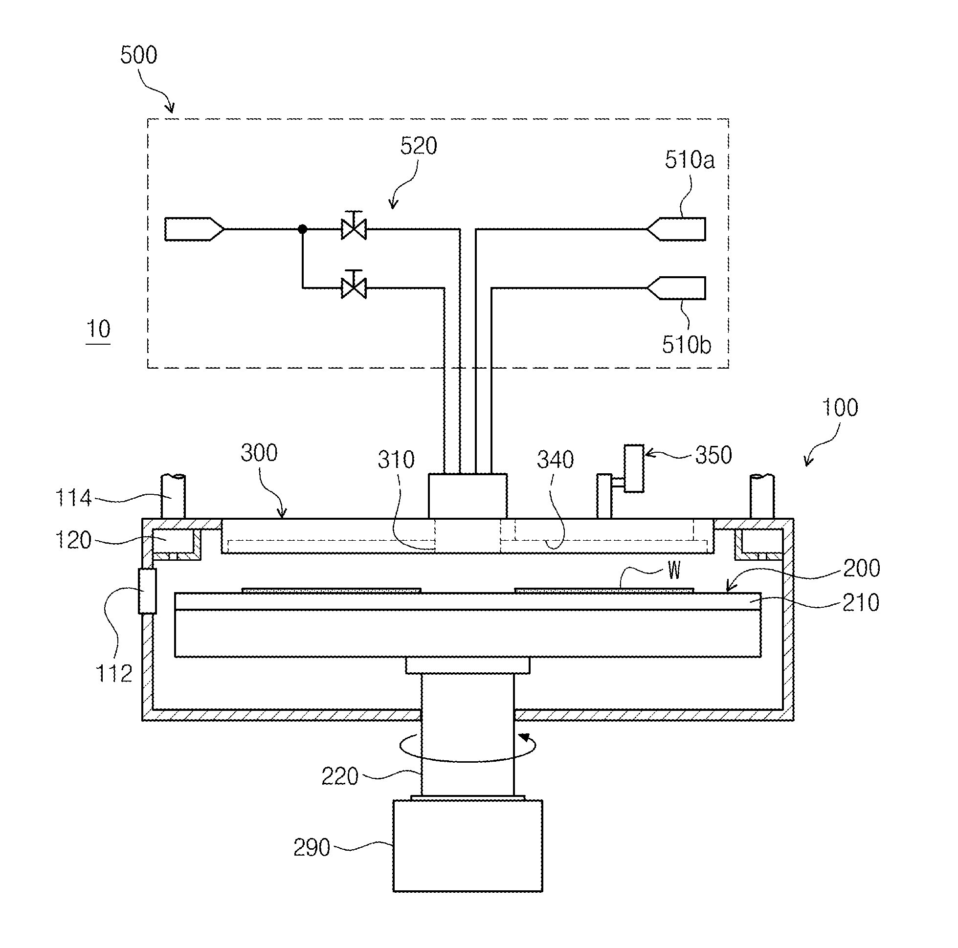
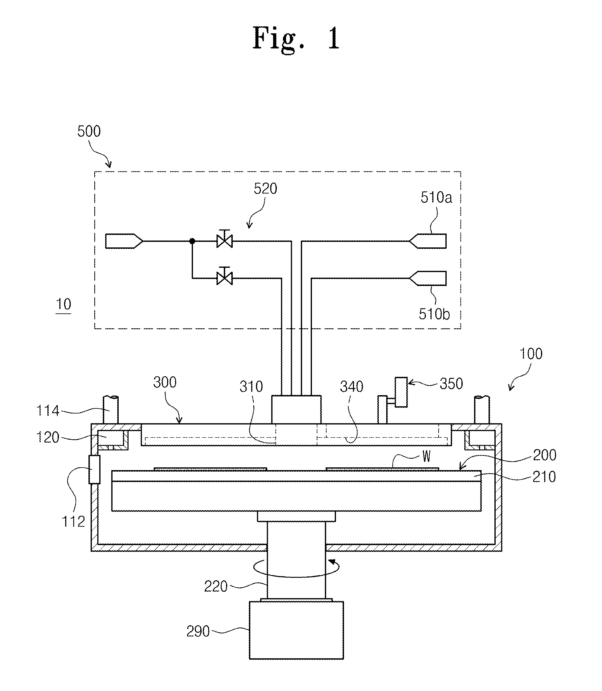
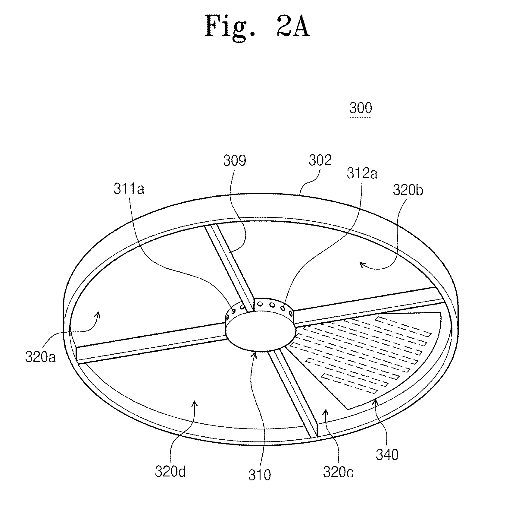
[0037]FIG. 1 is a schematic diagram of a deposition apparatus according to example embodiments of inventive concepts, FIGS. 2A and 2B are perspective and sectional views of the injection member of FIG. 1, and FIG. 3 is a plan view of the support member of FIG. 1.

[0038]Referring to FIGS. 1 through 3, a deposition apparatus 10 may include a process chamber 100, a support member 200, an injection member 300, and a supplying member 500.

[0039]The process chamber 100 may include an entrance 112 provided at one side thereof. During a process, wafers (or substrates) W may be loaded in or unloaded from the process chamber 100 through the entrance 112. The process chamber 100 may include a ventilation duct 120 and a ventilation conduit 114 that are configured to exhaust a reaction gas and a purge gas supplied into the process chamber 100 and by-products of reaction generated during a depositing process. In example embodiments, the ventilation duct 120 and the ventilation conduit 114 may be pr...


PUM

PropertyMeasurementUnit
Frequencyaaaaaaaaaa

Abstract

A plasma processing apparatus may include a process chamber configured to perform a plasma using process and contain a plurality of substrates, a support member provided in the process chamber, the substrates being laid on the same level of the support member, an injection member provided to face the support member and include a plurality of baffles, such that at least one reaction gas and a purge gas can be injected onto the substrates in an independent manner, and a driving part configured to rotate the support member or the injection member, such that the baffles of the injection member can orbit with respect to the plurality of the substrates laid on the support member. The injection member may include a plasma generator, which may be provided on at least one, configured to inject the reaction gas, of the baffles to turn the reaction gas into plasma.

Description

BACKGROUND OF THE INVENTION[0001]Embodiments of the inventive concepts relate to a thin film treatment apparatus to be used for manufacturing a semiconductor device, more particularly, to an injection member with a plasma generator and a plasma processing apparatus having the injection member.[0002]A plasma processing apparatus has been widely used for several processes, such as, a dry etching process, physical and chemical depositions, and a surface treatment process, for fabricating a semiconductor device.[0003]A conventional plasma processing apparatus is configured to include a first electrode connected to a showerhead and a second electrode connected to a chamber. In addition, the conventional plasma processing apparatus may further include surrounding parts, such as electrical interconnection part, noise shielding part, and a part for applying a plasma bias to a susceptor.[0004]Since conventional plasma processing apparatuses have a one-body type showerhead, it has been hard t...

Claims


Application Information

Patent Timeline
IPC IPC(8): H01L21/203H01L21/3065
CPCH01L21/203H01L21/3065C23C16/4584C23C16/4585C23C16/50H01J37/3244H01J37/32449H01J37/32633H01J37/32733C23C16/45563C23C16/45591H01J37/32568
Inventor PARK, YONG SUNGLEE, SUNG KWANGKIM, DONG YEULTOYODA, KAZUYUKIKASAHARA, OSAMUINADA, TETSUAKI
Owner KOOKJE ELECTRIC KOREA
Learn More