High frequency power supply device

Active Publication Date: 2020-04-16
MURATA MFG CO LTD
View PDF0 Cites 0 Cited by
  • Summary
  • Abstract
  • Description
  • Claims
  • Application Information

AI Technical Summary

Benefits of technology

[0019](11) In (10), it is preferable that the battery be an all-solid-state battery. Thus, the energy density of the battery can be significantly increased, and a long life span can be achieved by ensuring reliability and safety compared to a lithium-ion battery or the like. Consequently, a compact and long-life power supply apparatus with a high reliability can be configured.
[0020]According to the present

Problems solved by technology

In a high frequency power generation circuit in a high frequency power supply device that receives DC power supplied from a DC power supply and generates high frequency power, switching noise generated by high frequency switching of a switch element may return to the DC power supply side.
In such a case, not only is the switching noise transmitted through wiring or a line but noise may also be emitted by a high frequency current flowing in wiring in a circuit within the power supply

Method used


Image

  • High frequency power supply device
  • High frequency power supply device
  • High frequency power supply device

Examples


first embodiment

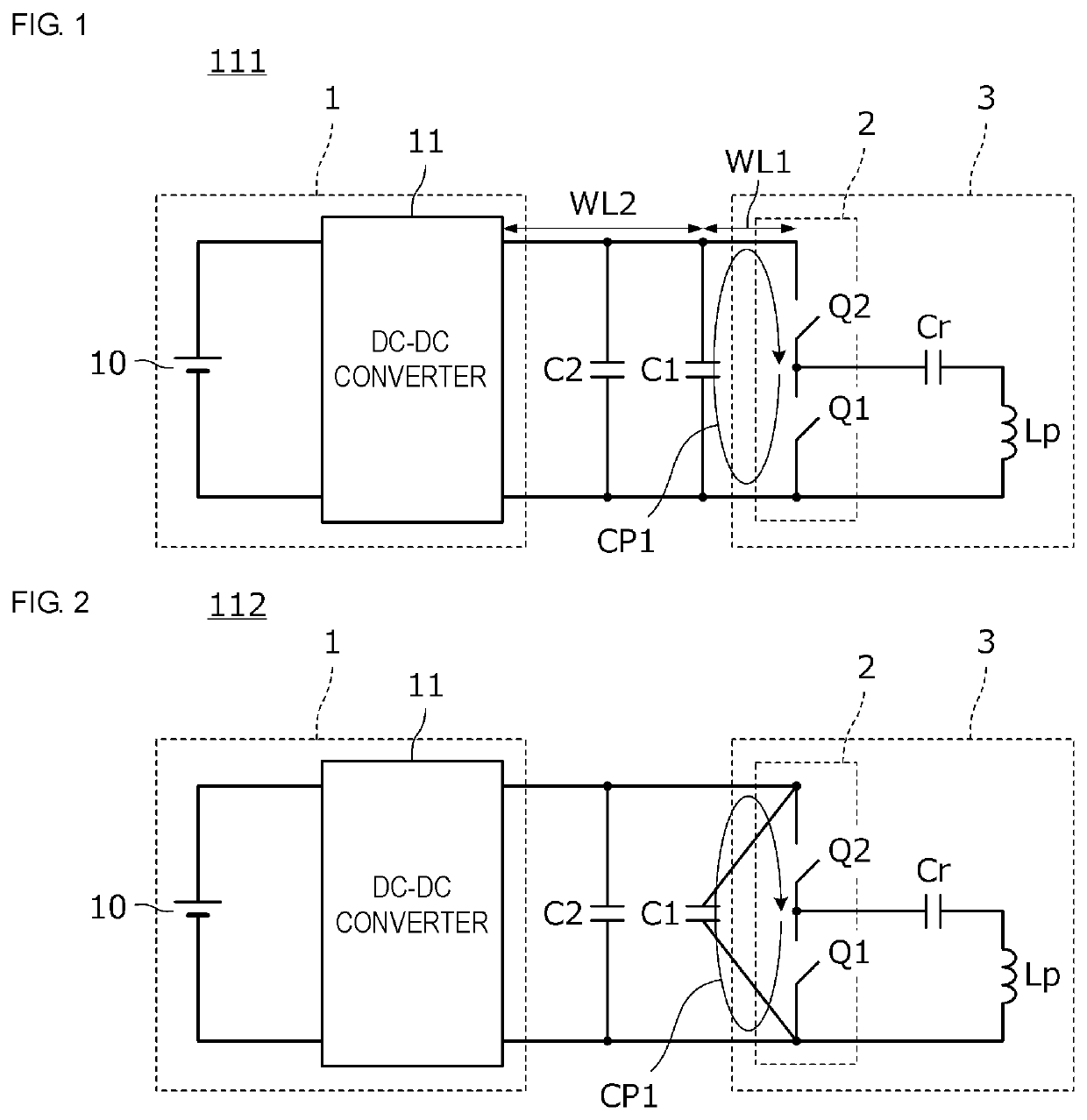
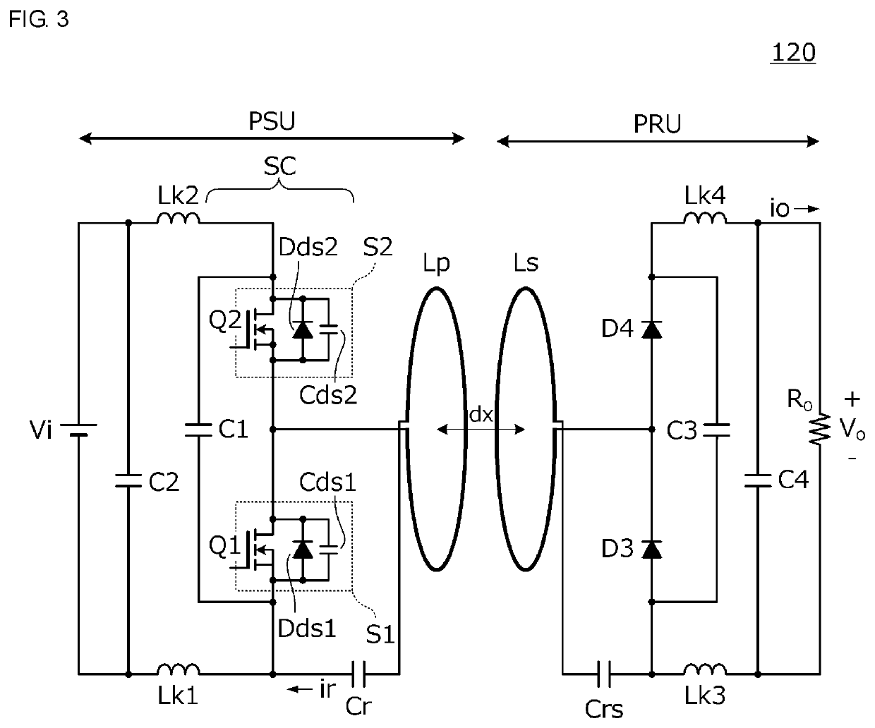
[0032]FIG. 1 is a circuit diagram of a high frequency power supply device 111 according to the first embodiment. The high frequency power supply device 111 is a power supplying device in a wireless power transfer system that includes a power transmission device and a power reception device. The high frequency power supply device 111 includes a DC power supply 1 and a high frequency power generation circuit 3 that is connected to the DC power supply 1 and generates high frequency power. The high frequency power generation circuit 3 includes a switching circuit 2 including a high-side switch element Q2 and a low-side switch element Q1, a power transmission coil Lp, and a resonant capacitor Cr. The power transmission coil Lp and the resonant capacitor Cr form a resonant circuit. The switch elements Q1 and Q2 are controlled by a switching control circuit, which is not illustrated in the drawing. The switch elements Q1 and Q2 are turned ON and turned OFF alternately with a dead time inte...

second embodiment

[0048]In a second embodiment, a more specific circuit configuration and operation of a switching circuit will be described.

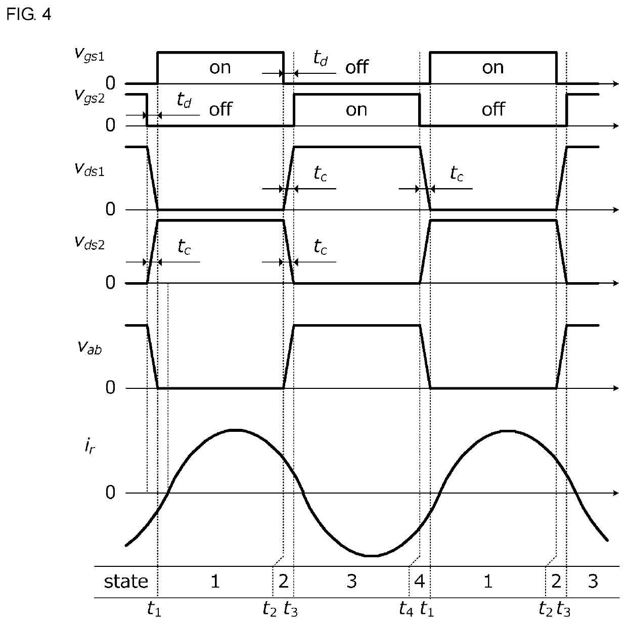
[0049]FIG. 3 is a circuit diagram of a power transfer system 120 that includes a high frequency power supply device according to the second embodiment.

[0050]The power transfer system 120 includes a power transmission device PSU and a power reception device PRU. The power transmission device PSU is an example of a “high frequency power supply device” according to the present disclosure.

[0051]The power transfer system 120 is a system in which the power transmission device PSU supplies stable DC energy to the power reception device PRU.

[0052]The power transmission device PSU includes a DC power supply Vi and a switching circuit SC that is connected to the DC power supply Vi and generates high frequency power. The switching circuit SC is an example of a “high frequency power generation circuit” according to the present disclosure.

[0053]The switching circuit SC inclu...

third embodiment

[0078]In a third embodiment, a configuration of a high frequency power supply device at a circuit substrate, in particular, a mounting structure of a switch element and a high frequency capacitor, will be described.

[0079]FIGS. 5A, 5B, 5C, and 5D are diagrams illustrating a mounting structure of a high frequency power supply device according to the third embodiment, in particular, a switch element and a high frequency capacitor at a circuit substrate. FIG. 5A is a perspective view viewed from a side of a circuit substrate 4 at which the high frequency capacitor C1, the high-side switch element Q2, and the low-side switch element Q1 are mounted. FIG. 5B is a cross-sectional view of the circuit substrate 4, FIG. 5C is a plan view of the circuit substrate 4, and FIG. 5D is a bottom view of the circuit substrate 4.

[0080]A circuit of the high frequency power supply device is configured as described in the first and second embodiments, and is formed at the circuit substrate 4. The high fre...


PUM


Abstract

A line length between an input end of a switching circuit and a high frequency capacitor is shorter than a line length between an output end of a DC power supply and the high frequency capacitor. A current path going through the switching circuit and the high frequency capacitor is the shortest among a plurality of current paths through which a switching current is caused to flow by switching at the switching circuit. Furthermore, the high frequency capacitor makes the ratio of time during which the voltage across the high-side switch element changes by a switching operation of the high-side switch element and the ratio of time during which the voltage across the low-side switch element changes by a switching operation of the low-side switch element the same, and thus reduces a harmonic wave current included in a current output from the high frequency power generation circuit.

Description

CROSS-REFERENCE TO RELATED APPLICATIONS[0001]This application claims benefit of priority to International Patent Application No. PCT / JP2018 / 023400, filed Jun. 20, 2018, and to Japanese Patent Application No. 2017-121856, filed Jun. 22, 2017, the entire contents of each are incorporated herein by reference.BACKGROUNDTechnical Field[0002]The present disclosure relates to a high frequency power supply device that includes a high frequency power generation circuit connected to a DC power supply and generating high frequency power using a switching circuit allowing a switch element to be switched at a high frequency.Background Art[0003]A power supply device that is connected to a DC power supply, converts the DC power supply into high frequency power using a switch element, and supplies power via the high frequency power is used for, for example, a wireless power transfer system, a POL (Point of Load) converter, and the like.[0004]For example, in WO 2012 / 101905, a power supply device tha...

Claims


Application Information

Patent Timeline
IPC IPC(8): H02M7/5387H02J50/12H02M1/12
CPCH02M2001/007H02M1/12H02M7/5387H02J50/12H02M1/44H02M1/14H02M1/126Y02B70/10H02J7/0063H02M1/0058H02M3/003H02M3/33571H02M3/01H02M1/007
Inventor HOSOTANI, TATSUYA
Owner MURATA MFG CO LTD
Why Eureka
Try Eureka