Variable compression ratio internal combustion engine

a compression ratio and internal combustion engine technology, applied in the direction of machines/engines, combustion air/fuel air treatment, mechanical equipment, etc., can solve the problems of large noise (noise) such as gear noise and clattering noise, and the problem of generating noise at the meshing section of the variable compression ratio internal combustion engine, so as to reduce noise

Inactive Publication Date: 2010-07-01
TOYOTA JIDOSHA KK
View PDF6 Cites 25 Cited by
  • Summary
  • Abstract
  • Description
  • Claims
  • Application Information

AI Technical Summary

Benefits of technology

[0007]The present invention is made in view of the aforesaid problem. The object of the invention is to provide a variable compression ratio internal combustion engine that can reduce noise which is heard at the outside of the variable compression ratio internal combustion engine.

Problems solved by technology

In a state in which the gear mechanism is driven, coarse large sound (noise) such as gear noise and clattering noise may be generated in some cases at a mesh section where the pair of gears are meshed with each other and at the compression ratio changing mechanism.
As described above, the conventional variable compression ratio internal combustion engine entails a problem of generating noise at the meshing section.
Further, this problem may occur when a different power transmission mechanism, such as a belt mechanism or the like, instead of the gear mechanism is used.

Method used


Image

  • Variable compression ratio internal combustion engine
  • Variable compression ratio internal combustion engine
  • Variable compression ratio internal combustion engine

Examples


Embodiment Construction

Construction

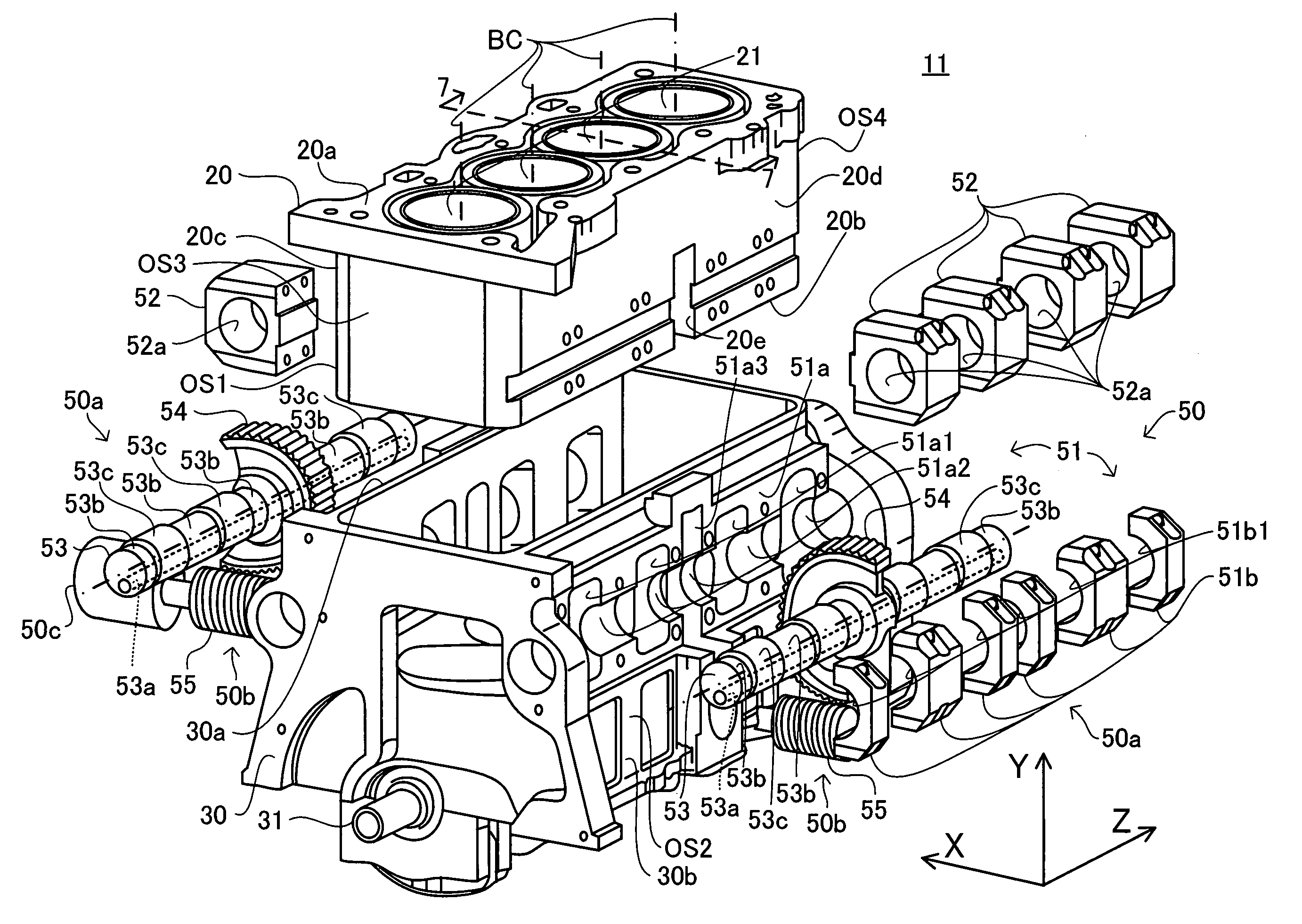
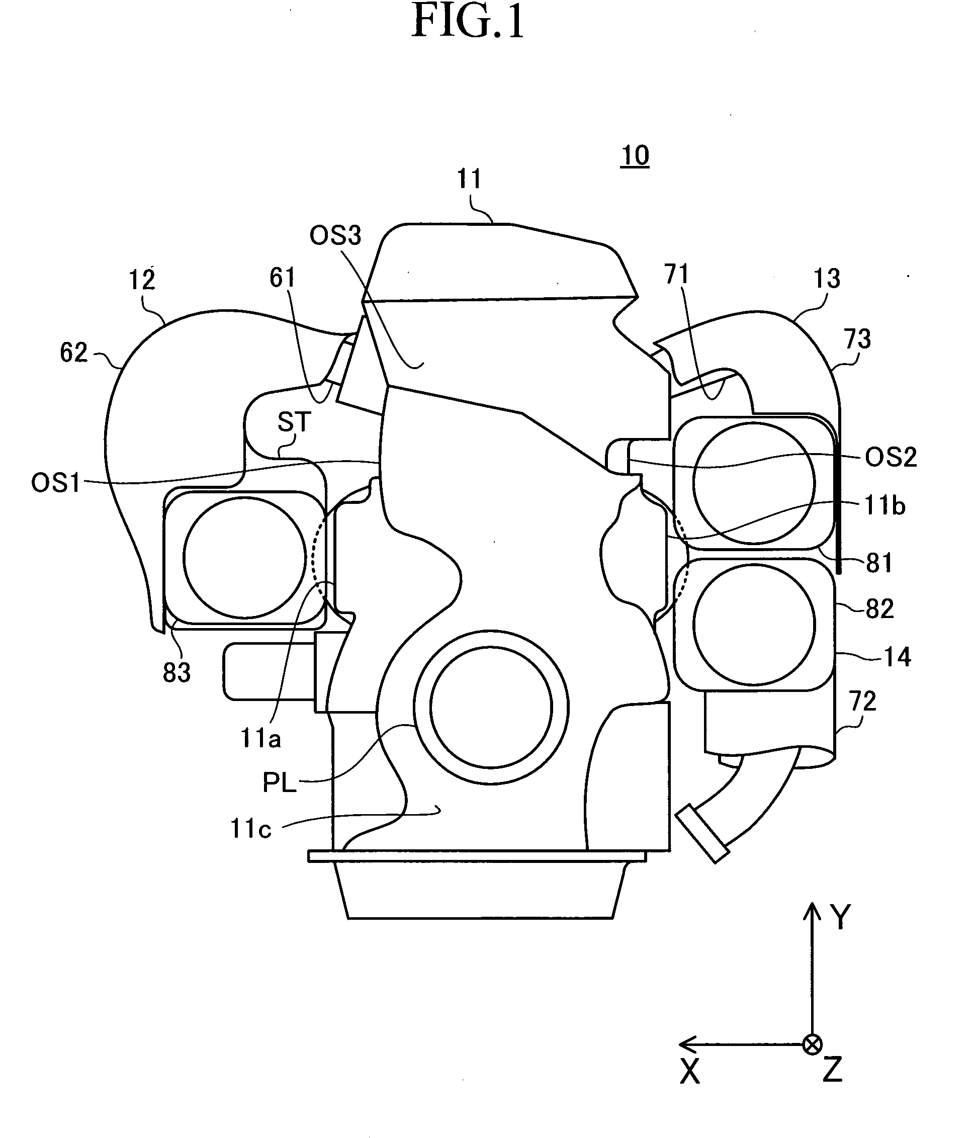
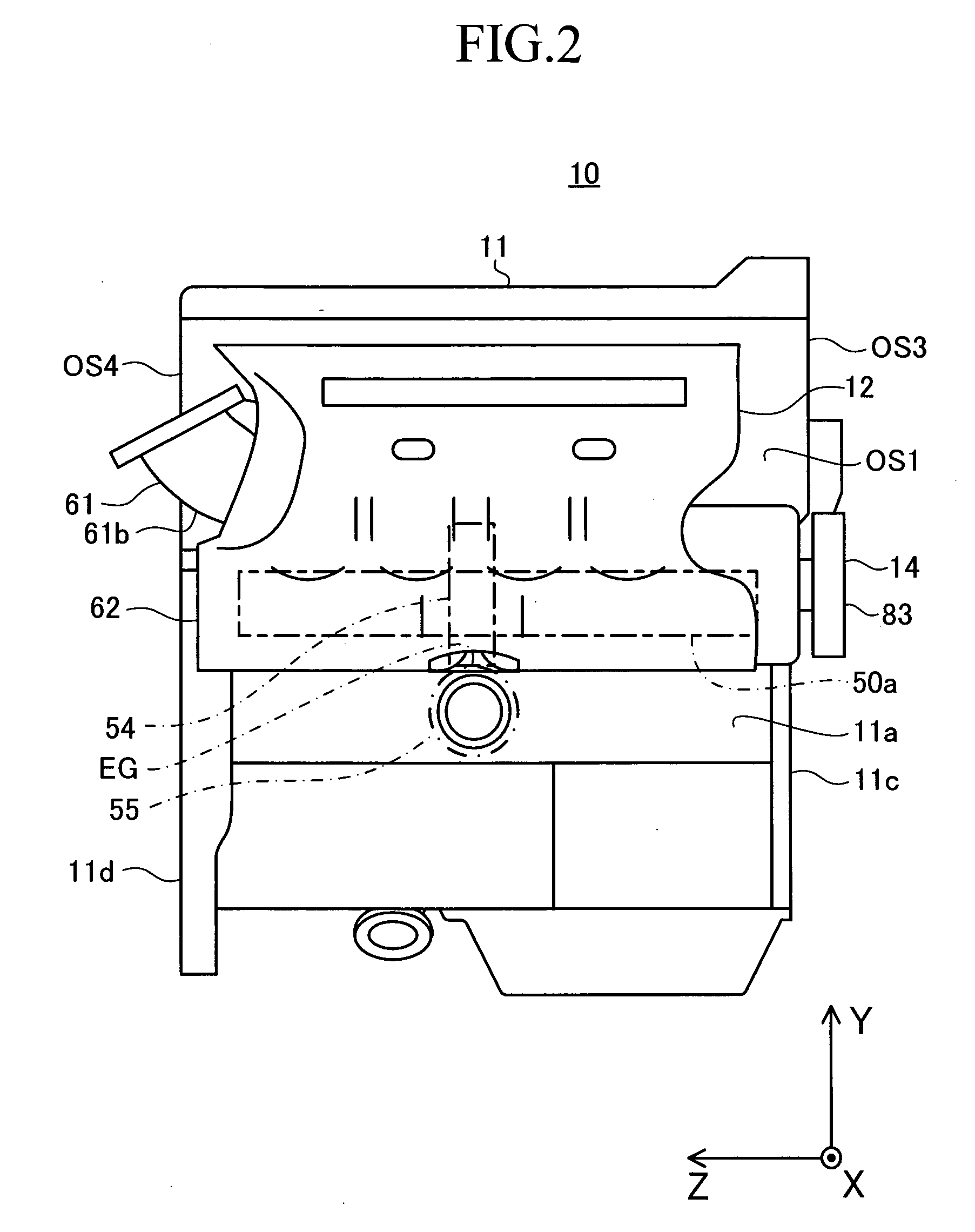
[0034]An embodiment of the variable compression ratio internal combustion engine according to the present invention will be described below with reference to FIGS. 1 to 3. As shown in FIGS. 1 to 3, the variable compression ratio internal combustion engine (internal combustion engine) 10 includes an engine main body 11, and an intake-system-constructing-section 12, an exhaust-system-constructing-section 13 and accessories section 14, these being fixed to the engine main body 11. The description is provided below using a rectangular coordinate with a right-hand system having an X-axis, Y-axis and Z-axis.

[0035]The engine main body 11 has generally a rectangular shape having four sidewall faces OS1 to OS4 as shown in FIG. 4 that illustrates the engine main body 11 of the internal combustion engine 10 from which the intake-system-constructing-section 12, the exhaust-system-constructing-section 13 and the accessories section 14 are removed (specifically, FIG. 4 illustrates onl...


PUM


Abstract

An internal combustion engine 10 comprises a device having a mechanism that moves a cylinder block relative to a crankcase, a worm wheel (wheel) 54 fixed to the mechanism, and a worm 55 meshed with the wheel. The device is disposed at the position in the vicinity of an disposed-face OS1 and within the OS3 disposed-face when the disposed-face is viewed from the front. The internal combustion engine drives the worm for rotatably driving the wheel to drive the mechanism. The internal combustion engine has a noise shielding members 61, 62, and 83 arranged so as to cover a meshing portion EG where the wheel and the worm are meshed with each other, when the disposed-face is viewed from the front. The noise generated at the meshing portion is attenuated by the noise shielding member, and propagated to the outside of the internal combustion engine. Consequently, the noise heard at the outside is reduced.

Description

BACKGROUND OF THE INVENTION[0001]1. Technical Field[0002]The present invention relates to a variable compression ratio internal combustion engine capable of changing a compression ratio that is a ratio of a maximum value to a minimum value of a volume of a combustion chamber, the volume changing with a reciprocal movement of a piston.[0003]2. Background Art[0004]A variable compression ratio internal combustion engine that can change a compression ratio has been conventionally known. The variable compression ratio internal combustion engine includes a compression ratio changing mechanism that is driven for moving a cylinder block relative to a crankcase in a direction of a center axis of a cylinder bore, a gear mechanism having a pair of gears that are meshed with each other, and a drive device for driving the gear mechanism. The gear mechanism is driven to drive the compression ratio changing mechanism. With this structure, when the gear mechanism is driven by the drive device, the ...

Claims


Application Information

Patent Timeline
Patent Type & Authority Applications(United States)
IPC IPC(8): F02B75/04F02M35/02F01N13/10
CPCF01N13/102F01N2260/20F02B75/041F02B77/13F02D15/04F02F7/008F02M35/10104F02M35/112F02B75/04F01N13/10
Inventor KAMIYAMA, EIICHI
Owner TOYOTA JIDOSHA KK
Why Eureka
Try Eureka