Rotor magnet positioning device

a positioning device and rotating magnet technology, applied in the direction of magnetic circuit rotating parts, magnetic circuit shape/form/construction, stator/rotor body manufacturing, etc., can solve the problem of difficult to overcome production tolerance problems

Active Publication Date: 2010-07-01
REGAL BELOIT AUSTRALIA PTY LTD
View PDF32 Cites 23 Cited by
  • Summary
  • Abstract
  • Description
  • Claims
  • Application Information

AI Technical Summary

Benefits of technology

[0009]The magnet positioning device in accordance with the invention provides significant advantages over prior art methods used for securing magnets to a rotor. The device includes recesses which may be specifically shaped to closely conform to the shape the magnets. This prevents movement of the magnets within the recesses and maintains a consistent spacing between the magnets, both during assembly of the rotor and during subsequent operation of the machine.
[0010]In the latter regard, it is to be noted that if adhesive is also used to secure the magnets to the rotor, the device may be removed from the rotor after the adhesive has cured. Given that the device maintains a consistent spacing between the magnets, there is now no danger of the magnets moving if the rotor is handled before the adhesive is properly cured. The device will retain the magnets in their correct positions.
[0011]Whilst the device may be removed from the assembled rotor, it is however preferably that it remains in place after the motor is fully assembled. In this way, the device assists in securing the magnets to the rotor during subsequent operation of the machine.

Problems solved by technology

This means that a part produced according to the invention would need to mate to a circular rotor and project a circular face into the air gap, which leads to production tolerance issues that are difficult to overcome.

Method used


Image

  • Rotor magnet positioning device
  • Rotor magnet positioning device
  • Rotor magnet positioning device

Examples


Embodiment Construction

[0050]Initially, it should be understood that throughout this description the terms “top” and “bottom” are used merely for convenience to refer to the embodiments shown in the accompanying drawings. It should accordingly be understood that these terms have no relevance to the orientation of the actual apparatus as it may be manufactured or used.

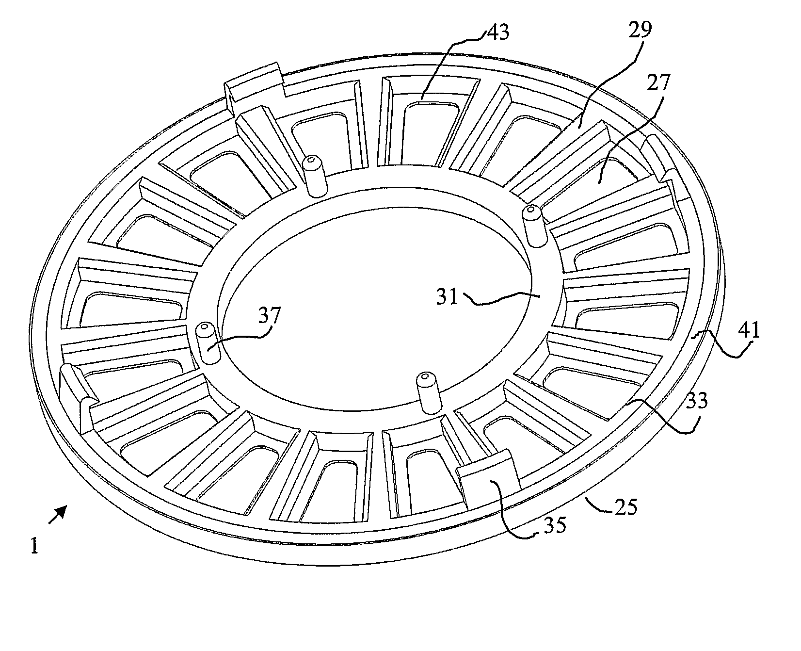
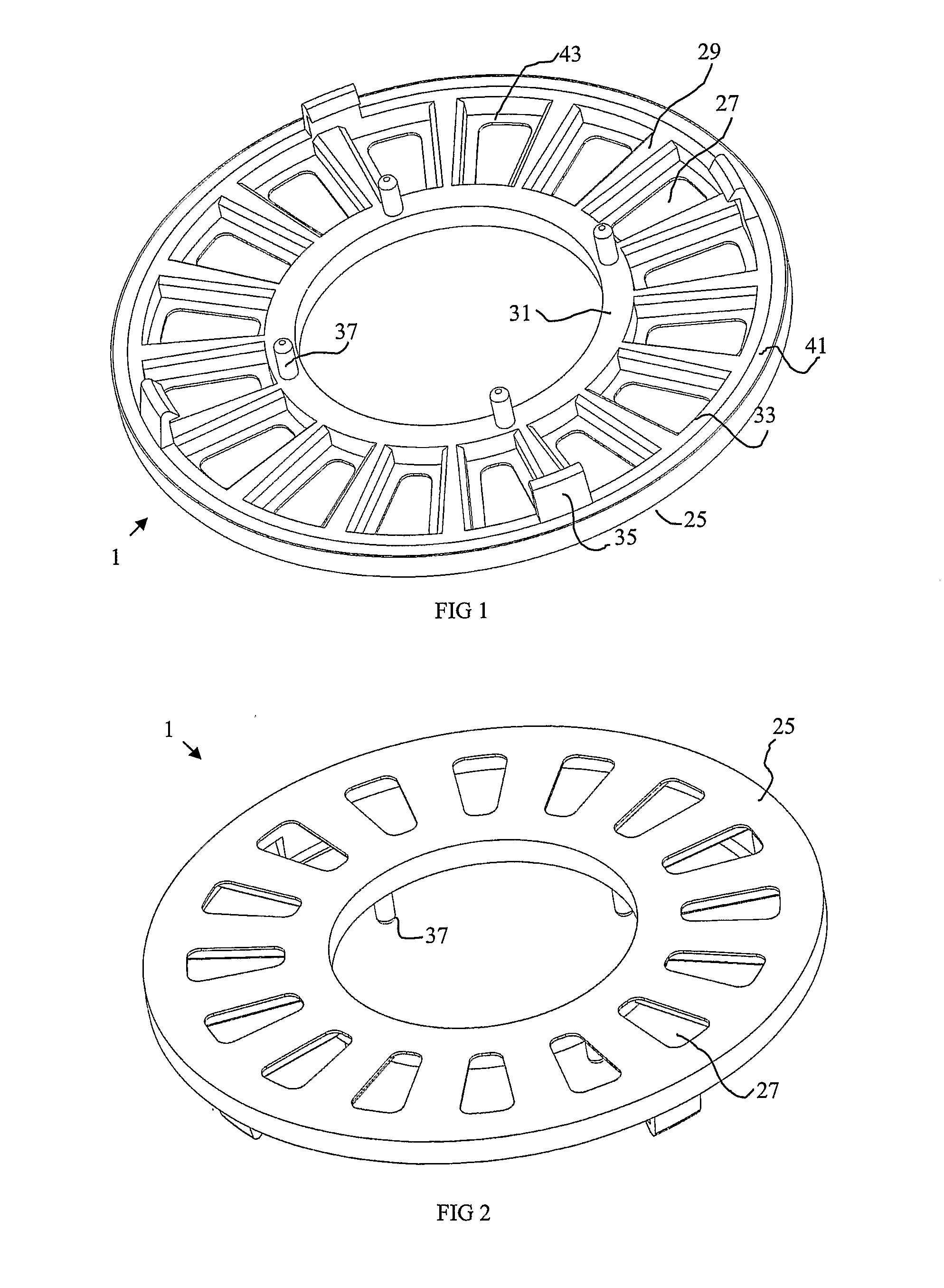
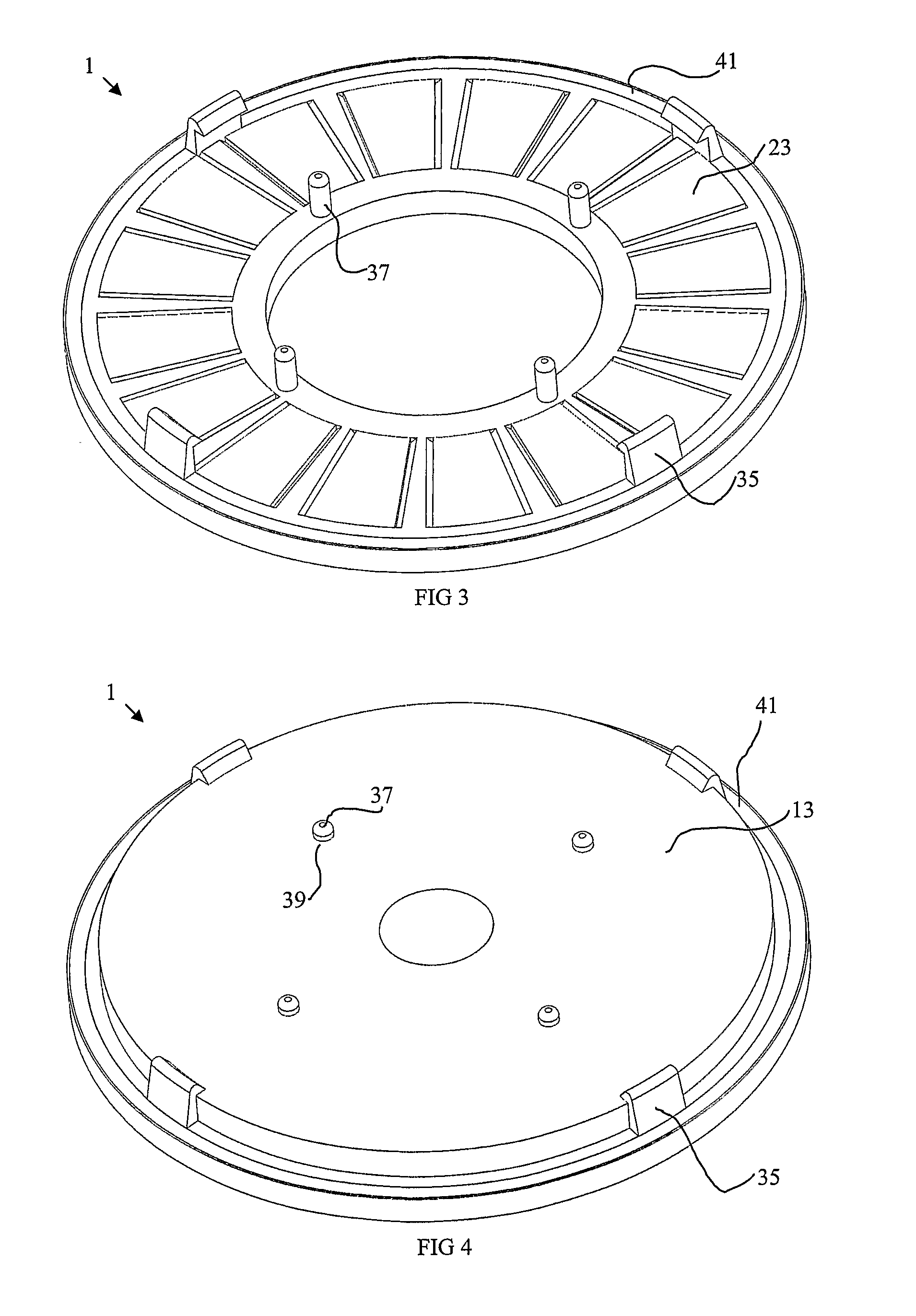
[0051]FIGS. 1 to 7 of the drawings show a preferred embodiment of the present invention. In particular, FIGS. 1 and 2 show bottom and top perspective views, respectively, of a magnet positioning device 1 for use in a permanent magnet axial flux electric motor 3, as shown in FIGS. 6 and 7.

[0052]The components of the motor can be best seen in the exploded view shown in FIG. 7. These components include a housing, incorporating end shields 5 and 7 and a side wall 9, a stator 11 (although the windings are not shown in the drawings) mounted within the housing. A rotor disc 13 is mounted on a shaft 15 which is rotatable within the housing by means o...


PUM

PropertyMeasurementUnit
weightsaaaaaaaaaa
non-electrically-conductiveaaaaaaaaaa
magnetic forcesaaaaaaaaaa

Abstract

A device for positioning a planar array of magnets within a permanent magnet electrical machine of the type having a rotor and stator with an air gap there between. The device includes a body made of non-ferrous material and having a first side which is attachable to the rotor and a second side which, in an assembled machine, faces the air gap. The first side of the body has a plurality of recesses therein for receiving a corresponding plurality of magnets. The recesses are shaped and arranged to separate the magnets from each other and maintain a consistent spacing between them. When the device is attached to the rotor the magnets are held in a fixed position against the rotor. The electrical machine may be a motor or a generator.

Description

FIELD OF THE INVENTION[0001]The present invention relates generally to permanent magnet electrical machines including a planar array of magnets. In particular, the invention relates to a device for positioning magnets on a rotor of a permanent magnet electrical machine. The device is especially suited for use in axial flux electric motors and it will be convenient to describe the invention in relation to that example application. It should be understood however that the device is also suitable for other forms of electrical machine that incorporate a planar array of magnets, such as linear motors or generators.BACKGROUND OF THE INVENTION[0002]In a permanent magnet electric machine the magnets are often secured to the rotor in a planar array by an adhesive. Positioning of the magnets on the rotor is a difficult and time consuming exercise because the magnets tend to be attracted to each other or repel each other, depending upon the orientation of the magnets. It is therefore important...

Claims


Application Information

Patent Timeline
Patent Type & Authority Applications(United States)
IPC IPC(8): H02K1/28H02K15/03
CPCH02K1/2793H02K21/24H02K1/28Y10T29/49012H02K15/03H02K1/2795
Inventor LANGFORD, CHARLES RICHARDCAMILLERI, STEVEN PETERPATTERSON, DEAN JAMES
Owner REGAL BELOIT AUSTRALIA PTY LTD
Why Eureka
Try Eureka