Light source driving circuit

a driving circuit and light source technology, applied in the direction of light sources, electrical equipment, instruments, etc., can solve the problems of light source scintillation, unsatisfactory electrical safety of the conventional light source driving circuit, and user's risk of electric shock during the operation of the brightness adjustment signal, so as to reduce light source scintillation and enhance electrical safety

Inactive Publication Date: 2010-07-01
DELTA ELECTRONICS INC
View PDF3 Cites 12 Cited by
  • Summary
  • Abstract
  • Description
  • Claims
  • Application Information

AI Technical Summary

Benefits of technology

[0008]It is an object of the present invention to provide a light source driving circuit having enhanced electrical safety and reduced light source scintillation when the light-emitting element is driven by the light source driving circuit.

Problems solved by technology

Since the control circuit of the conventional light source driving circuit is connected to the utility power through the primary winding assembly of the transformer and the brightness adjusting signal is directly transmitted to the control circuit, the user has a risk of getting an electric shock during the process of operating the brightness adjusting signal.
In other words, the electrical safety of the conventional light source driving circuit is unsatisfactory.
Moreover, since the time period of switching the brightness adjusting signal from the enabling signal to the disabling signal or the time period of switching the brightness adjusting signal from the disabling signal to the enabling signal is very short, a problem of causing light source scintillation will occur when the cold cathode fluorescent lamp or the light emitting diode is driven by the conventional light source driving circuit.

Method used


Image

  • Light source driving circuit
  • Light source driving circuit
  • Light source driving circuit

Examples


first embodiment

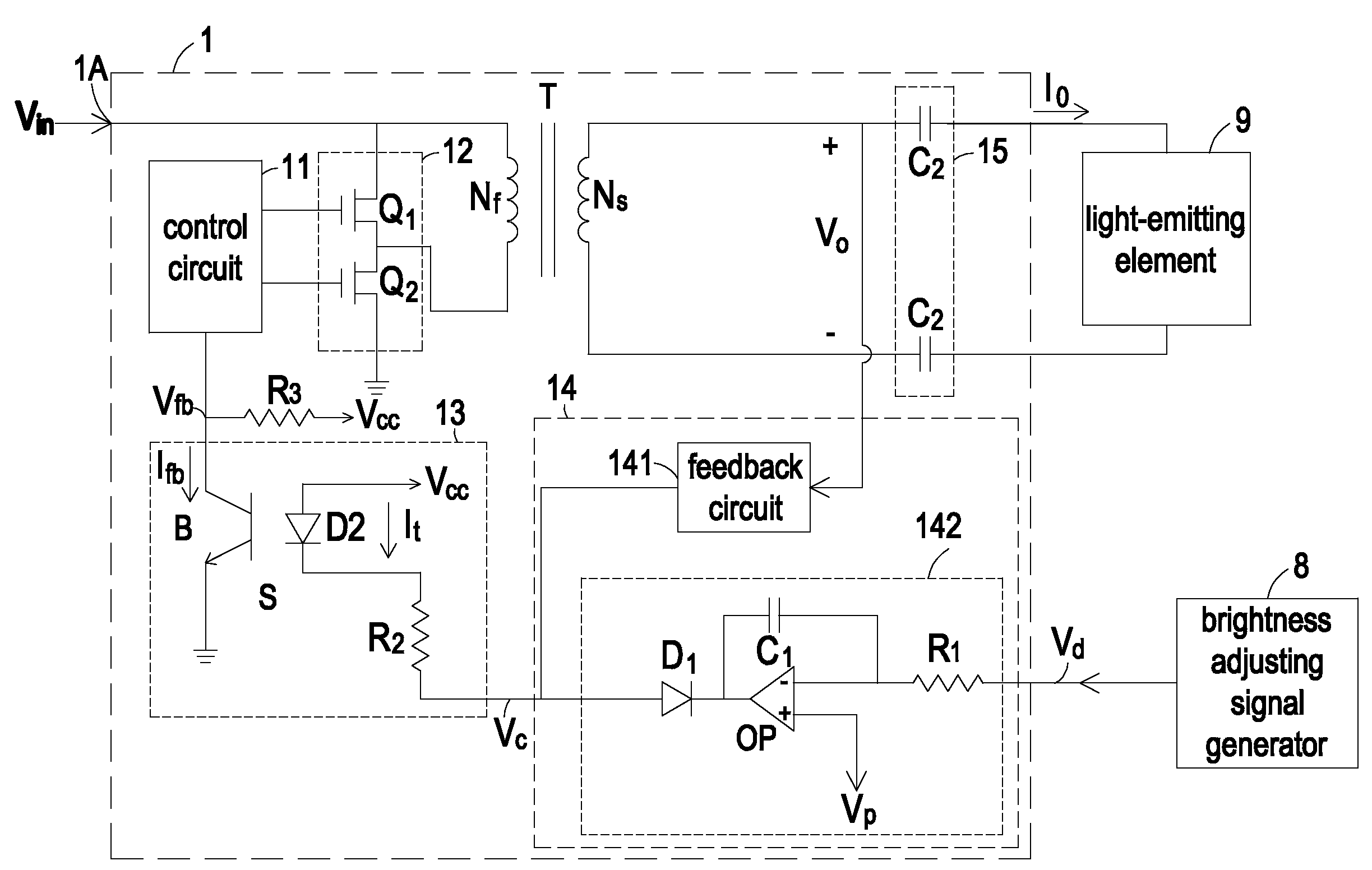
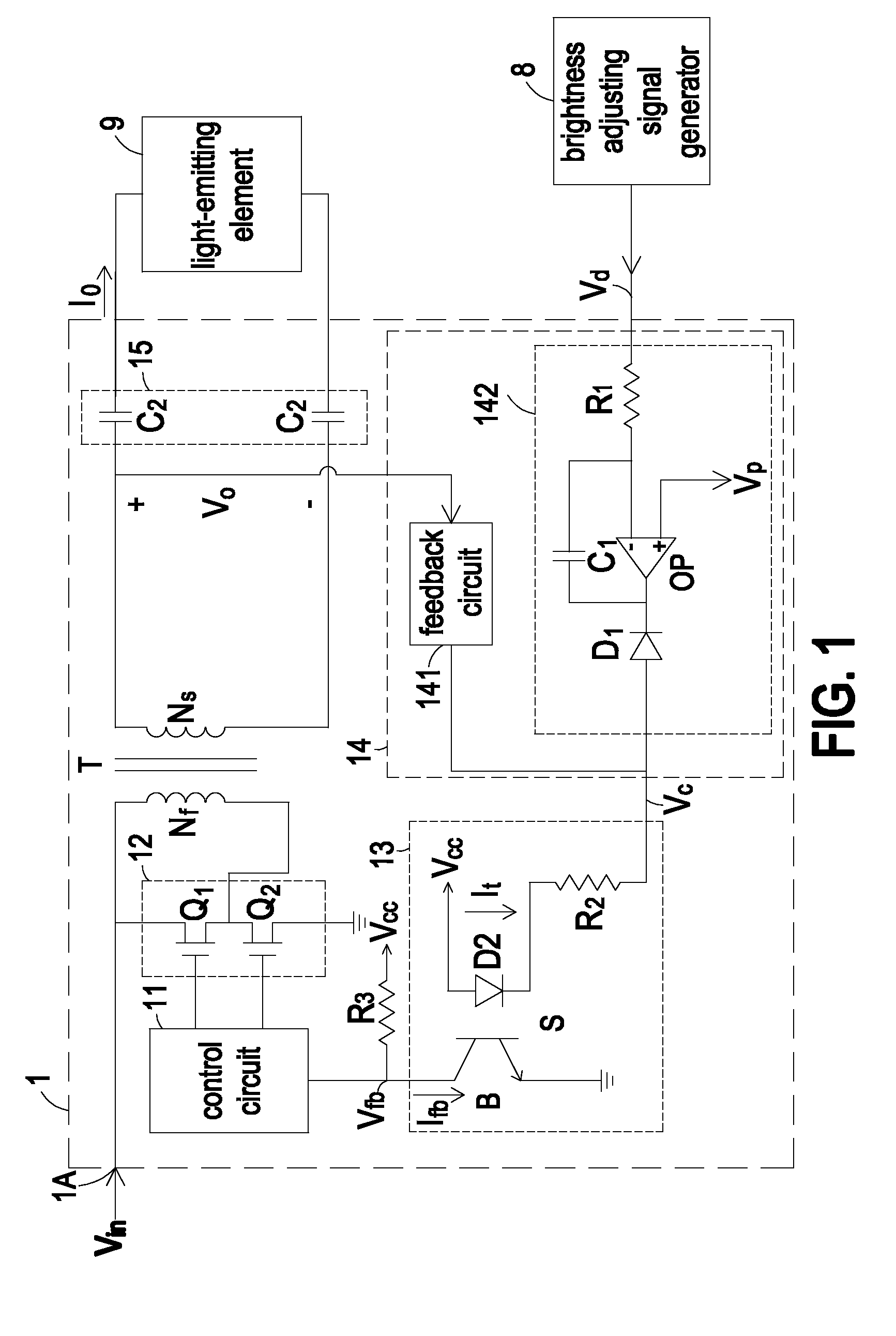
[0019]FIG. 1 is a schematic circuit diagram of a light source driving circuit according to the present invention. As shown in FIG. 1, the light source driving circuit 1 is electrically connected to at least a light-emitting element 9. An example of the light-emitting element 9 includes a cold cathode fluorescent lamp (CCFL) or a light emitting diode (LED). An input voltage Vin (e.g. utility power) is converted by the light source driving circuit 1 into an output voltage Vo required for illuminating the light-emitting element 9. Furthermore, the light source driving circuit 1 is electrically connected to a brightness adjusting signal generator 8. The brightness adjusting signal generator 8 is used for generating a brightness adjusting signal Vd. According to the brightness adjusting signal Vd, the light source driving circuit 1 can adjust the brightness value of the light emitted by the light-emitting element 9. The brightness adjusting signal Vd includes alternate enabling signal an...

second embodiment

[0036]FIG. 4 is a schematic circuit diagram of a light source driving circuit according to the present invention. As shown in FIG. 4, the brightness adjusting circuit 14 of the light source driving circuit 1 further comprises a compensating circuit 16. The input terminal of the compensating circuit 16 is connected to the brightness adjusting signal generator 8. The output terminal of the compensating circuit 16 is connected to the brightness adjusting signal converting circuit 142. The compensating circuit 16 is used for increasing the duration of the enabling signal of the brightness adjusting signal Vd, thereby generating a compensated brightness adjusting signal Vd′ to the brightness adjusting circuit 14. Under this circumstance, the brightness adjusting circuit 14 generates a control signal Vc according to the compensated brightness adjusting signal Vd′ and the output voltage Vo. Even if the control circuit 11 fails to precisely control operations of the switching circuit 12 due...


PUM


Abstract

A light source driving circuit includes a transformer, a switching circuit, a control circuit, a brightness adjusting circuit and an isolator circuit. The brightness adjusting circuit is connected to a secondary winding assembly of the transformer and the light-emitting element for detecting an output voltage and/or an output current and generating a control signal according to the brightness adjusting signal. The isolator circuit is used for isolating the primary winding assembly of the transformer from the brightness adjusting circuit. The isolator circuit generates a feedback current according to the control signal. According to the feedback current, the switching circuit is controlled by the control circuit. As a status of the brightness adjusting signal is changed, a status of the control signal is changed and a time period of changing the status of the control signal is longer than a time period of changing the status of the brightness adjusting signal.

Description

FIELD OF THE INVENTION[0001]The present invention relates to a light source driving circuit, and more particularly to a light source driving circuit for enhancing safety and reducing light source scintillation when the light-emitting element is driven by the light source driving circuit.BACKGROUND OF THE INVENTION[0002]In recent years, cold cathode fluorescent lamps (CCFLs) and light emitting diodes (LEDs) have been widely used. In comparison with the common incandescent lamps, LEDs or CCFLs have an increased illuminating efficiency and an extended service life. With the maturity of the LED and CCFL technology, LEDs or CCFLs will replace all conventional lighting facilities. Until now, LEDs or CCFLs are widely used in many aspects of daily lives, such as household lighting device, automobile lighting devices, handheld lighting devices, backlight sources for LCD panels, traffic lights, indicator board displays, and the like.[0003]Generally, the cold cathode fluorescent lamp or the li...

Claims


Application Information

Patent Timeline
Patent Type & Authority Applications(United States)
IPC IPC(8): H05B41/16
CPCH05B33/0818H05B33/0848H05B41/2827H05B41/3927H05B45/14H05B45/382
Inventor CHANG, SHIH-HSIENHSIEH, MING-CHIH
Owner DELTA ELECTRONICS INC
Why Eureka
Try Eureka