Drop Coating Apparatus

Inactive Publication Date: 2010-07-01
SHARP KK
View PDF6 Cites 9 Cited by
  • Summary
  • Abstract
  • Description
  • Claims
  • Application Information

AI Technical Summary

Benefits of technology

[0031]In the droplet applying apparatus of this embodiment, the droplet ejecting sections are fitted on the one flat surface of the one beam member opposite to the other flat surface confronting the other beam member as well as on the one flat surface of the other beam member opposite to the other flat surface confronting the one beam member. Therefore, the droplet ejecting sections are fitted on outer flat surfaces of the integrally coupled two beam members that are on the outer side in the other direction. Therefore, fitting and removal, maintenance, and other working processes of the droplet ejecting sections can easily be executed from th

Problems solved by technology

However, the line head system would be unsuitable for recovery of color filter substrates as shown in, for example, JP 2003-66218 A. JP 2003-66218 A shows a system which includes, as part of the manufacturing method of color filter substrates, ejecting a color filter material only to failure points on occurrence of coloring failure portions in the color filter substrate.
Using the line head system as a means for correcting such failure points scattered on the color filter substrate would involve the same processing time as in the ejection of droplets to all over the substrate, and moreover cause most of the nozzles to be non-operating nozzles that perform almost no ejecting operation, leading to a high likelihood of occurrence of nozzle clogging.
Further, maintenance operation would be required for all the nozzles, leading to increases in unnecessary waste fluids.
Also, with

Method used


Image

  • Drop Coating Apparatus
  • Drop Coating Apparatus
  • Drop Coating Apparatus

Examples


Embodiment Construction

[0072]Hereinbelow, the present invention will be described in detail by embodiments thereof illustrated in accompanying drawings.

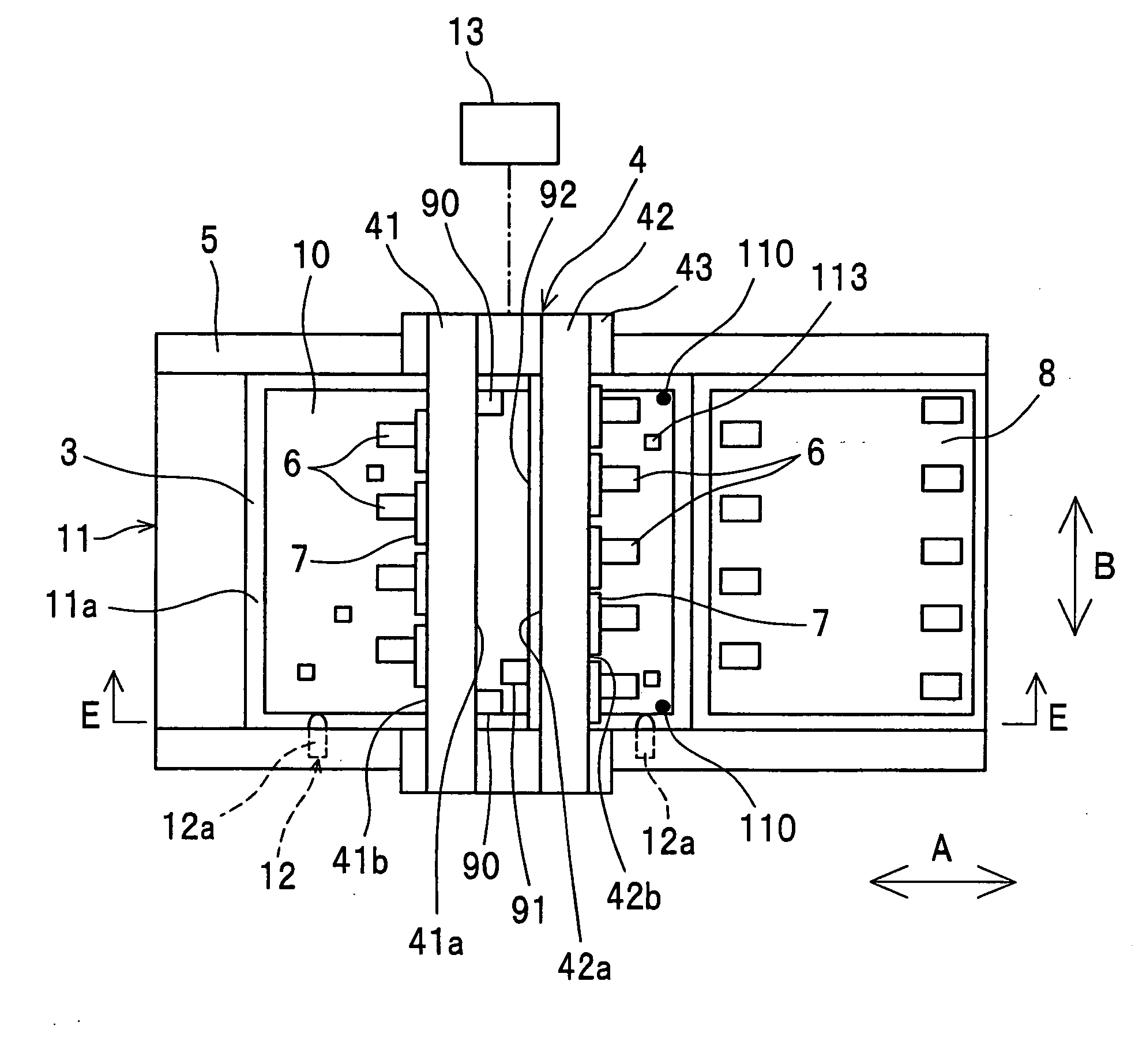
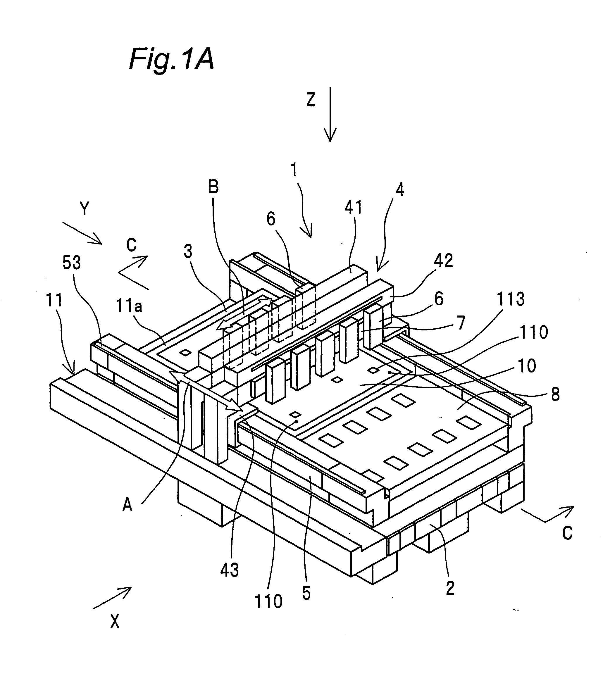
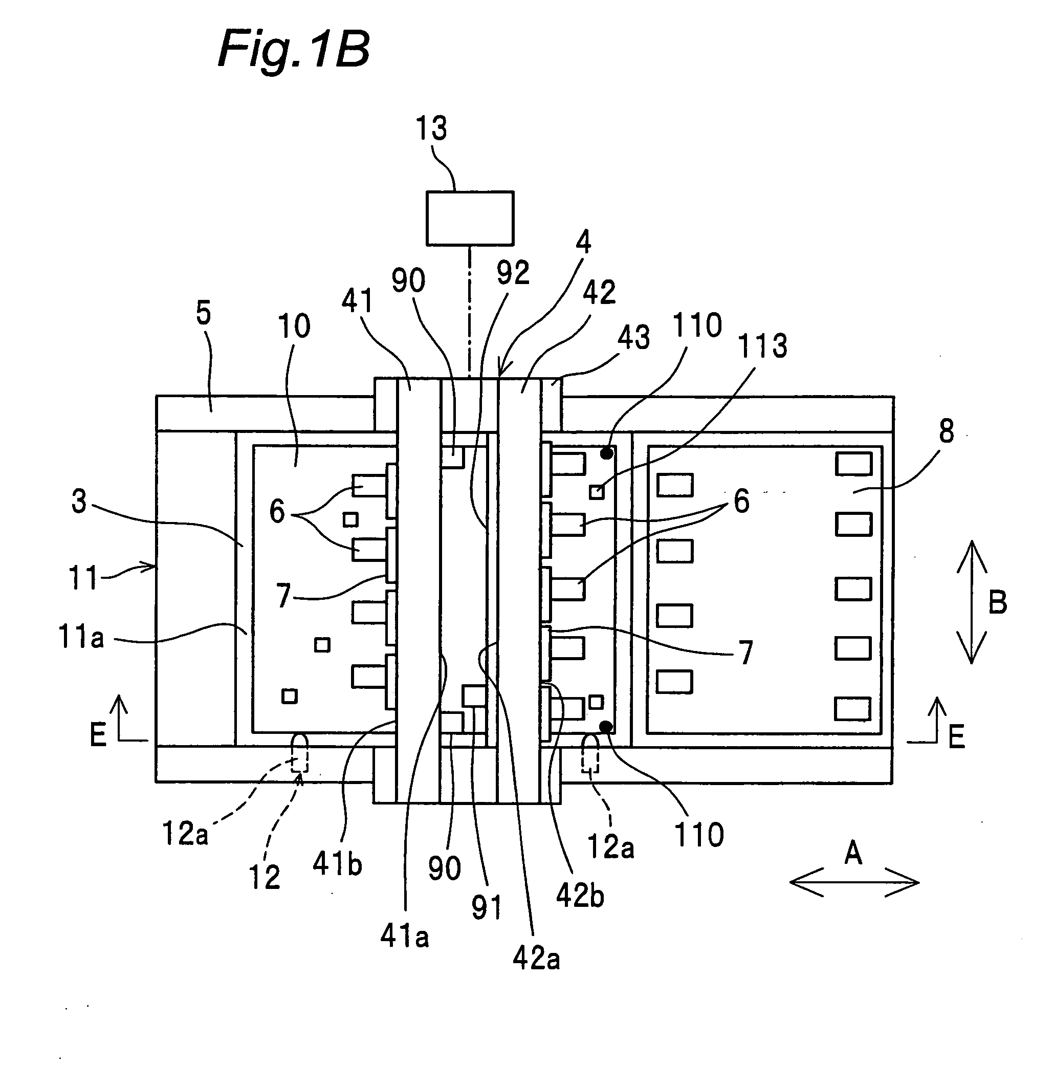
[0073]FIGS. 1A and 1B are constructional views showing an embodiment of the droplet applying apparatus of the invention. The droplet applying apparatus 1 of the invention includes a base 11 having a mounting surface 11a on which a substrate 10 is to be mounted, an arm part 4 which is fitted to the base 11 so as to be movable relative to the base 11, and a plurality of droplet ejecting sections 6 which are movably fitted to the arm part 4 and which eject droplets to the substrate 10 mounted on the mounting surface 11a.

[0074]The substrate 10 is, for example, a color filter substrate to be used for liquid crystal displays or the like. The substrate 10 has defect portions 113 such as coloring failures. Two alignment marks 110 are formed near end faces of the substrate 10. The alignment marks 110 have only to be at least two in quantity.

[0075]The base 11 has a...


PUM


Abstract

A droplet applying apparatus includes a base 11 having a mounting surface 11a on which a substrate 10 is to be mounted, an arm part 4 which is fitted to the base 11 so as to be movable relative to the base 11 in an arrow A direction, and a plurality of droplet ejecting sections 6 which are fitted to the arm part 4 so as to be movable in an arrow B direction and which eject droplets to the substrate 10 mounted on the mounting surface 11a. The droplet ejecting sections 6 are fitted on a fitting surface 41b of a first beam member 41 of the arm part 4 as well as on a fitting surface 42b of a second beam member 42 of the arm part 4.

Description

TECHNICAL FIELD[0001]The present invention relates to a droplet applying apparatus for applying droplets onto a substrate by an ink jet system or the like.BACKGROUND ART[0002]In recent years, the ink jet technology has been expected for use as manufacturing apparatuses, not merely as printer devices for forming images on paper mediums. For example, in JP 2003-191462 A, an apparatus construction in which droplet ejecting elements using the ink jet system are mounted is disclosed as a manufacturing apparatus for liquid crystal displays, organic EL displays, plasma displays, electron emission elements, electrophoretic display devices and the like. For improvement of landing position precision onto the substrate, in JP 2003-191462 A, a stage for carrying the substrate in one fixed direction with an apparatus base body provided by a granite surface plate, and a carriage mechanism for moving an ink jet head along a direction perpendicular to the stage traveling direction, are provided on ...

Claims


Application Information

Patent Timeline
IPC IPC(8): B41J2/01
CPCB41J3/28H01L21/6715B05C5/00
Inventor NAKAJIMA, YOSHINORIHIGUCHI, KAORUTAMURA, TOSHIHIRO
Owner SHARP KK
Why Eureka
Try Eureka