Imaging apparatus with strobe consecutive shooting mode

a technology of imaging apparatus and shooting mode, which is applied in the direction of exposure control, instruments, television systems, etc., can solve the problems of inability to obtain exposure sufficient for shooting, the voltage accumulated in the capacitor decreases, etc., and achieves the effect of preventing the degradation of image quality

Inactive Publication Date: 2010-07-01
CASIO COMPUTER CO LTD
View PDF19 Cites 45 Cited by
  • Summary
  • Abstract
  • Description
  • Claims
  • Application Information

AI Technical Summary

Benefits of technology

[0011]According to the present invention, since imaging elements are driven by pixel addition, it is possible to prevent the image quality from being deteriorated during strobe consecutive shooting.

Problems solved by technology

However, if strobe light is consecutively flashed, the voltage accumulated in a capacitor decreases.
Accordingly, exposure sufficient for shooting cannot be obtained.

Method used


Image

  • Imaging apparatus with strobe consecutive shooting mode
  • Imaging apparatus with strobe consecutive shooting mode
  • Imaging apparatus with strobe consecutive shooting mode

Examples


first embodiment

A. First Embodiment

[0023]A-1. Configuration of the Digital Camera

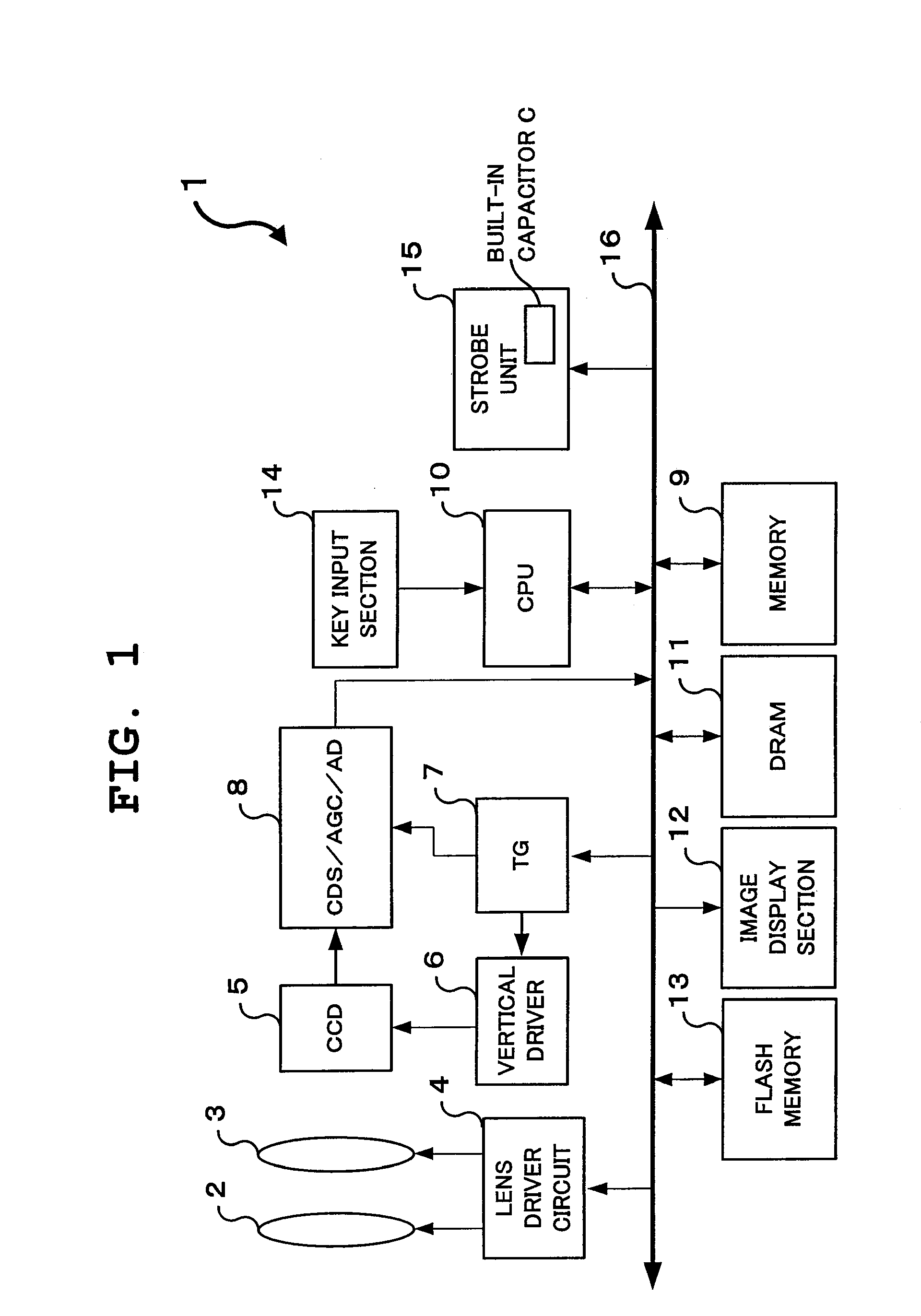
[0024]FIG. 1 is a block diagram showing the general electrical outline configuration of a digital cameral 1 which actualizes the imaging apparatus of the present invention.

[0025]The digital camera 1 includes a focus lens 2, a zoom lens 3, a lens driver circuit 4, a CCD 5, a vertical driver 6, a timing generator (TG) 7, a pre-processing unit 8, a memory 9, a CPU 10, a DRAM 11, an image display section 12, a flash memory 13, a key input section 14, a strobe unit 15, and a bus 16.

[0026]The focus lens 2 and the zoom lens 3 are configured with a plurality of lens groups, and the lens driver circuit 4 is connected to the focus lens 2 and the zoom lens 3.

[0027]The lens driver circuit 4 is configured by motors (not shown) for moving the focus lens 2 and the zoom lens 3 in the axial directions thereof, respectively, and motor drivers (not shown) for driving the focus motor and the zoom motor, respectively, according to a contro...


PUM


Abstract

When the mode is set to a strobe consecutive shooting mode, an imaging apparatus sets the mode to a pixel addition drive mode for reading out image data using pixel addition drive, performs metering operation using preliminary flashing and calculates an appropriate amount of flashing on the basis of the metering operation. Next, the imaging apparatus judges whether or not it is possible to flash three times consecutively with the calculated amount of flashing. If it is judged that it is not possible to flash three times consecutively with the calculated amount of flashing, the imaging apparatus limits the amount of flashing to the largest amount of flashing within the range of amounts of flashing with which flashing of strobe light three times consecutively is possible, and performs strobe consecutive shooting with the limited amount of flashing.

Description

CROSS-REFERENCE TO RELATED APPLICATION[0001]The present application is a Divisional Application of U.S. application Ser. No. 11 / 635,949 filed Dec. 8, 2006, which is based upon and claims the benefit of priority from the prior Japanese Patent Application No. 2005-355964 filed on Dec. 9, 2005, the entire contents of which are incorporated herein by reference.BACKGROUND OF THE INVENTION[0002]1. Field of the Invention[0003]The present invention relates to an imaging apparatus and an imaging method, and specifically to an imaging apparatus and an imaging method for shooting an object by flashing strobe light .[0004]2. Description of the Related Art[0005]In an imaging apparatus, for example, a digital camera, of recent years, strobe light needs be flashed for each shooting in the case where an object is to be shot consecutively in a dark condition.[0006]However, if strobe light is consecutively flashed, the voltage accumulated in a capacitor decreases. Accordingly, exposure sufficient for...

Claims


Application Information

Patent Timeline
Patent Type & Authority Applications(United States)
IPC IPC(8): G03B15/03G03B7/16G03B15/05H04N5/238H04N101/00
CPCG03B15/06H04N5/2354H04N23/74G03B15/00H04N23/70
Inventor MURAKAMI, TOMOHIKOKATO, YOSHIYUKISATO, TAKESHI
Owner CASIO COMPUTER CO LTD
Why Eureka
Try Eureka