
Display device with composite backlight module

Active Publication Date: 2010-07-01
HANNSTAR DISPLAY CORPORATION
View PDF4 Cites 5 Cited by
  • Summary
  • Abstract
  • Description
  • Claims
  • Application Information

AI Technical Summary

Benefits of technology

[0007]Therefore, it is a primary objective of the present invention to provide a display device with composite backlight module to reduce the number of components, simplify the manufacturing procedure, and lower the material cost effectively.
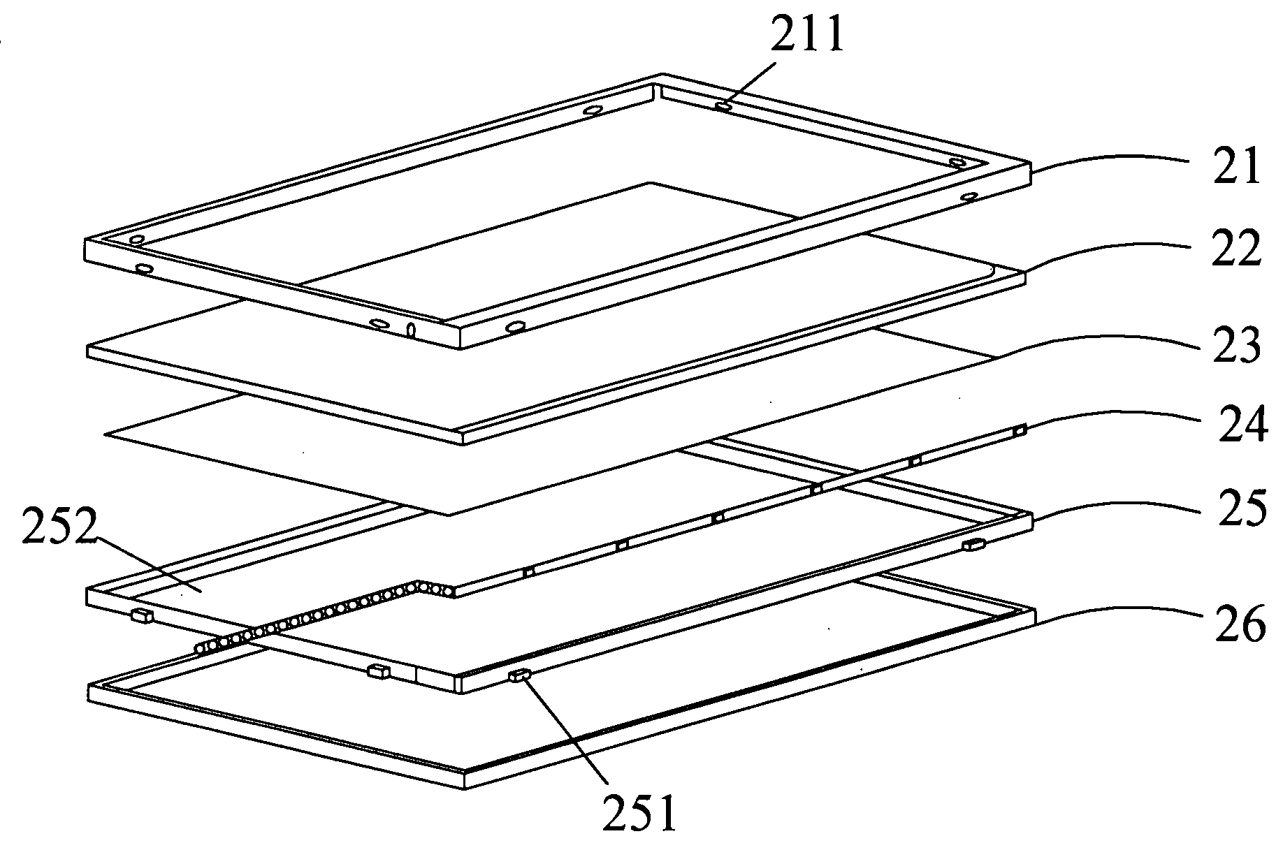
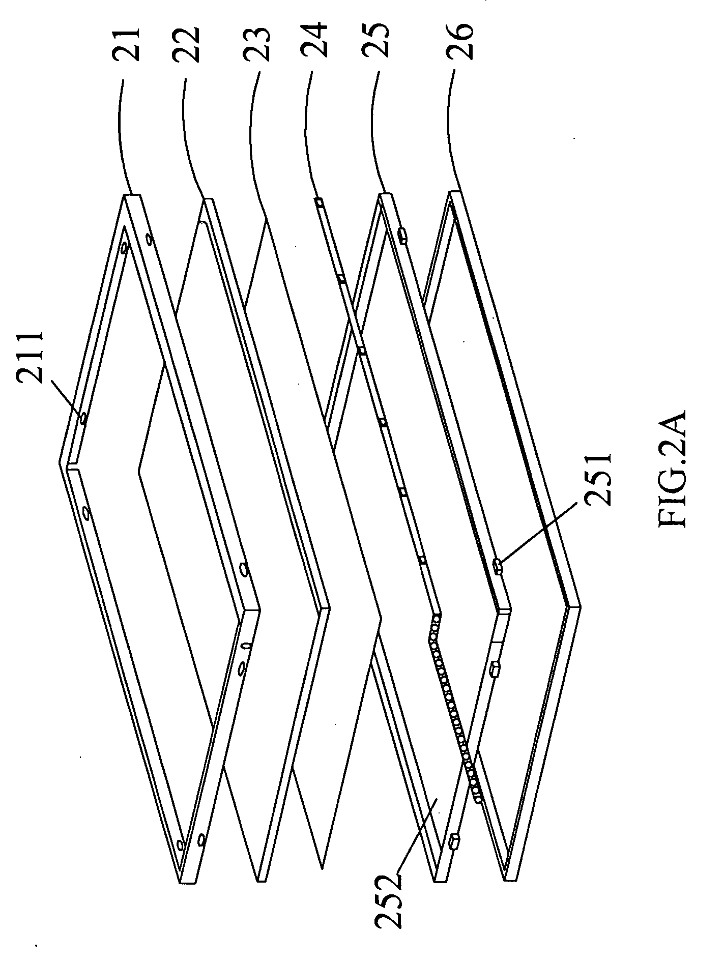
[0008]To achieve the foregoing objective, the present invention provides a liquid display device with composite backlight module, comprising: a bezel, a cell, at least one film, a light bar and a composite backlight module. The bezel includes a plurality of first connecting structures, and the light bar provides a light source to the cell, and the light bar includes at least one light emitting diode and a printed circuit board or a cold cathode fluorescent lamp (CCFL). The composite backlight module includes a plurality of second connecting structures and a containing space, and the second connecting structures are installed on an outer lateral side of the composite backlight module for engageing with the first connecting structures on a lateral side of the bezel. The containing space includes a first recessed portion, a second recessed portion and a third recessed portion. The dimension of the first recessed portion is corresponding to the dimension of the film for accommodating the film, and the dimension of the second recessed portion is corresponding to the dimension of the cell for accommodating the cell. The third recessed portion is disposed under the second recessed portion and in a slender shape for placing the light bar. In addition, the open region area of the second recessed portion is greater than an open region area of the first recessed portion; the open region area of first recessed portion is greater than an open region area of the third recessed portion. The composite backlight module includes a light guide portion for guiding light emitted by the light bar toward a light exit surface of the composite backlight module, and the light exit surface is arranged corresponding to the display surface of the cell, and the film uniformizes a light and supplies a uniformly distributed light source to the cell. The reflector is disposed at the bottom and the periphery of the composite backlight module for reflecting light emitted toward the bottom of the composite backlight module to enhance the utility rate of the light.
[0009]The present invention further provides a display device with composite backlight module, characterized in that a conventional light guide plate (LGP), backcover and a frame are integrated to form the composite backlight module, and the advantage of injection molding (capable of molding modules in various different shapes) effectively integrates the light guide plate (LGP), the backcover and the frame as a whole, and all of the aforementioned three components are integrated by the injection molding process. The composite backlight module still maintains the original mechanical characteristics of each component and effectively simplifies three components into a component module. Therefore, the composite backlight module simply requires the injection molding process once, and the present invention uses the same material to produce the composite backlight module, and thus the invention not only reduces the components and materials, but also simplifies the manufacturing procedure and lowers the cost effectively.

Problems solved by technology

As electronic technologies advances and portable electronic products become popular in our daily life, the demand for light, thin, short and compact display devices of low power consumption increases with time.
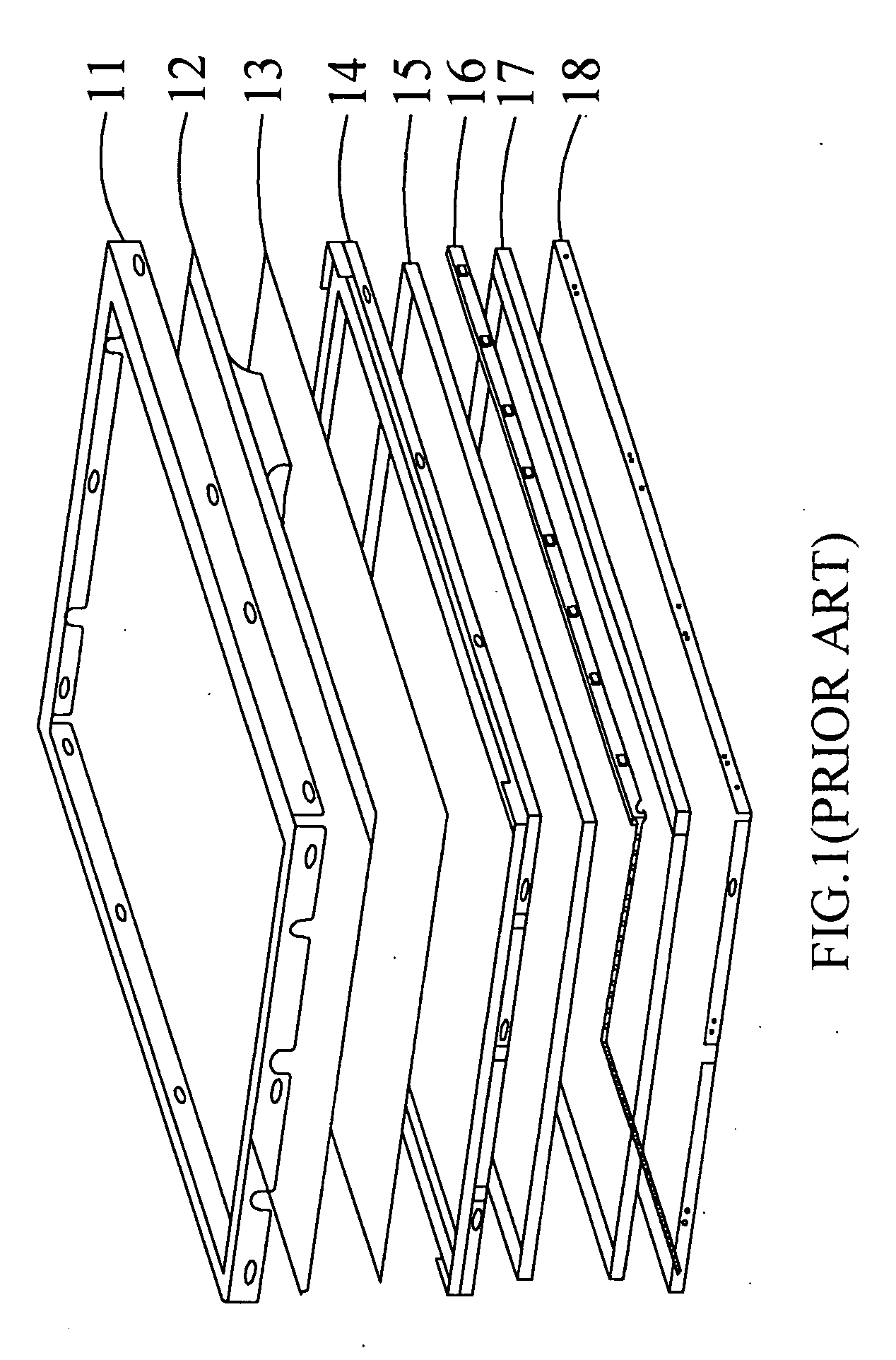
However, the cost of the backlight module occupies a relatively large percentage of the total cost of the LCD modules and the percentage of the total cost becomes increasingly higher as the dimension increases.
In addition, the components of the backlight module are very complicated, and the cost of each component becomes a burden, and the complicated components also increase the level of complexity for assembling the backlight modules.
As a result, the manufacturing procedure in the production line is extended to increase the level of difficulty and the consumption of materials of the backlight modules, and thus increasing the material cost.

Method used


Image

  • Display device with composite backlight module
  • Display device with composite backlight module
  • Display device with composite backlight module

Examples


Embodiment Construction

[0015]The present invention will become apparent from the description of a preferred embodiment of a display device with composite backlight module and the illustration of the related drawings, and it is noteworthy to point out that same elements mentioned in the preferred embodiment are numbered with the same numerals respectively.

[0016]With reference to FIG. 2A for an exploded view of a display device with composite backlight module in accordance with a preferred embodiment of the present invention, the display device comprises a bezel 21, a cell 22 diposed under the bezel 21, at least one film 23 disposed under the cell 22, a light bar 24 and a composite backlight module 25. The bezel 21 includes a plurality of first connecting structures 211, and the light bar 24 is provided for supplying a light source to the cell 22, and the light bar 24 includes at least one light emitting diode and a printed circuit board, wherein the light bar 24 can be a cold cathode fluorescent lamp. The ...


PUM


Abstract

The present invention discloses a display device comprising a bezel, a cell, at least one film, a light bar and a composite backlight module. The composite backlight module comprises a plurality of connecting structures coupled with the bezel for fixing and protecting the cell, a containing space for containing the cell and the film, and a light guide portion for guiding light emitted by the light bar to a light exit surface of the composite backlight module. The composite backlight module is made of a same material by injection molding.

Description

BACKGROUND OF THE INVENTION[0001]1. Field of the Invention[0002]The present invention generally relates to a display device, and more particularly to a display device with composite backlight module.[0003]2. Description of the Related Art[0004]As electronic technologies advances and portable electronic products become popular in our daily life, the demand for light, thin, short and compact display devices of low power consumption increases with time. Since liquid crystal display (LCD) has advantages of low power consumption, small amount of generated heat, and lightweight feature, LCDs are commonly used in electronic products and gradually replace traditional cathode ray tube (CRT) display devices. Since liquid crystal cells are not self-emitting devices, therefore it is necessary to have a backlight module to uniformize the light for providing a uniformly distributed light source. However, the cost of the backlight module occupies a relatively large percentage of the total cost of ...

Claims


Application Information

Patent Timeline
IPC IPC(8): G02F1/13357
CPCG02F1/133308G02F2001/133325G02F2001/133328G02F1/133325G02F1/133328
Inventor CHAN, WEI-JUNGTENG, CHIA-FENG
Owner HANNSTAR DISPLAY CORPORATION
Learn More