Refractive index distribution measurement method and refractive index distribution measurement apparatus
a technology of refractive index and measurement method, which is applied in the direction of optical apparatus testing, instruments, structural/machine measurement, etc., can solve the problems of deteriorating an optical characteristic of an optical element, unsatisfactory refractive index distribution, and inability to maintain predetermined optical characteristics, etc., to achieve high-precision measurement of internal refractive index distribution.
- Summary
- Abstract
- Description
- Claims
- Application Information
AI Technical Summary
Benefits of technology
Problems solved by technology
Method used
Image
Examples
first embodiment
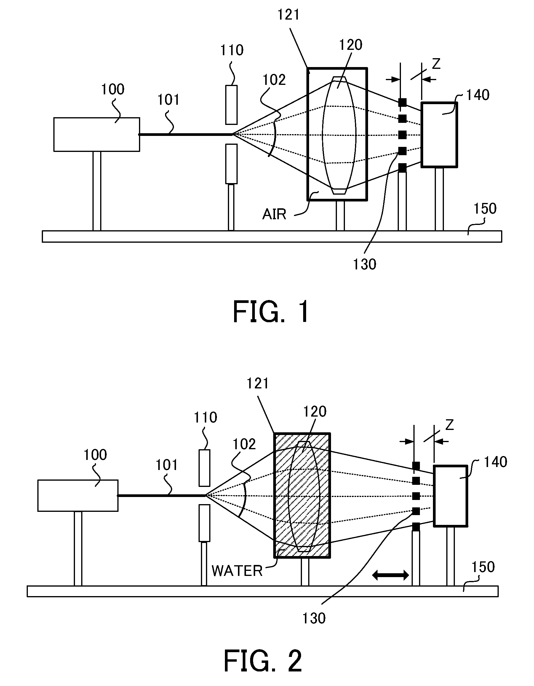
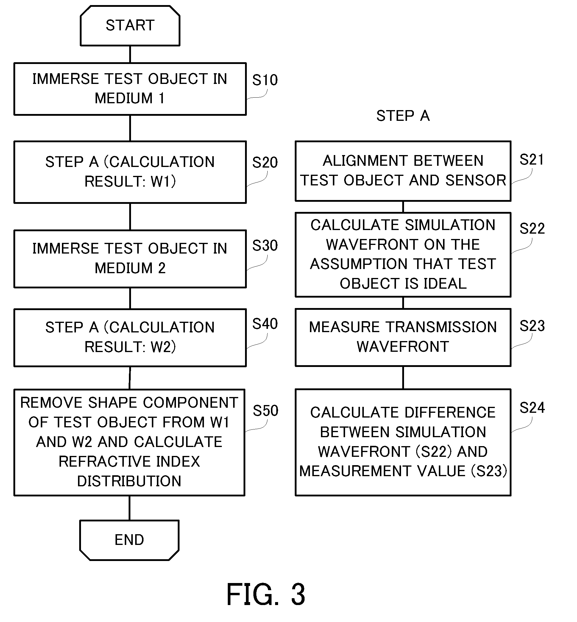
[0023]In this embodiment, a description will be given of a refractive index distribution measurement method for obtaining an internal refractive index distribution of a test object by immersing the test object in two types of media (air and water) and by measuring a transmission wavefront for each medium.
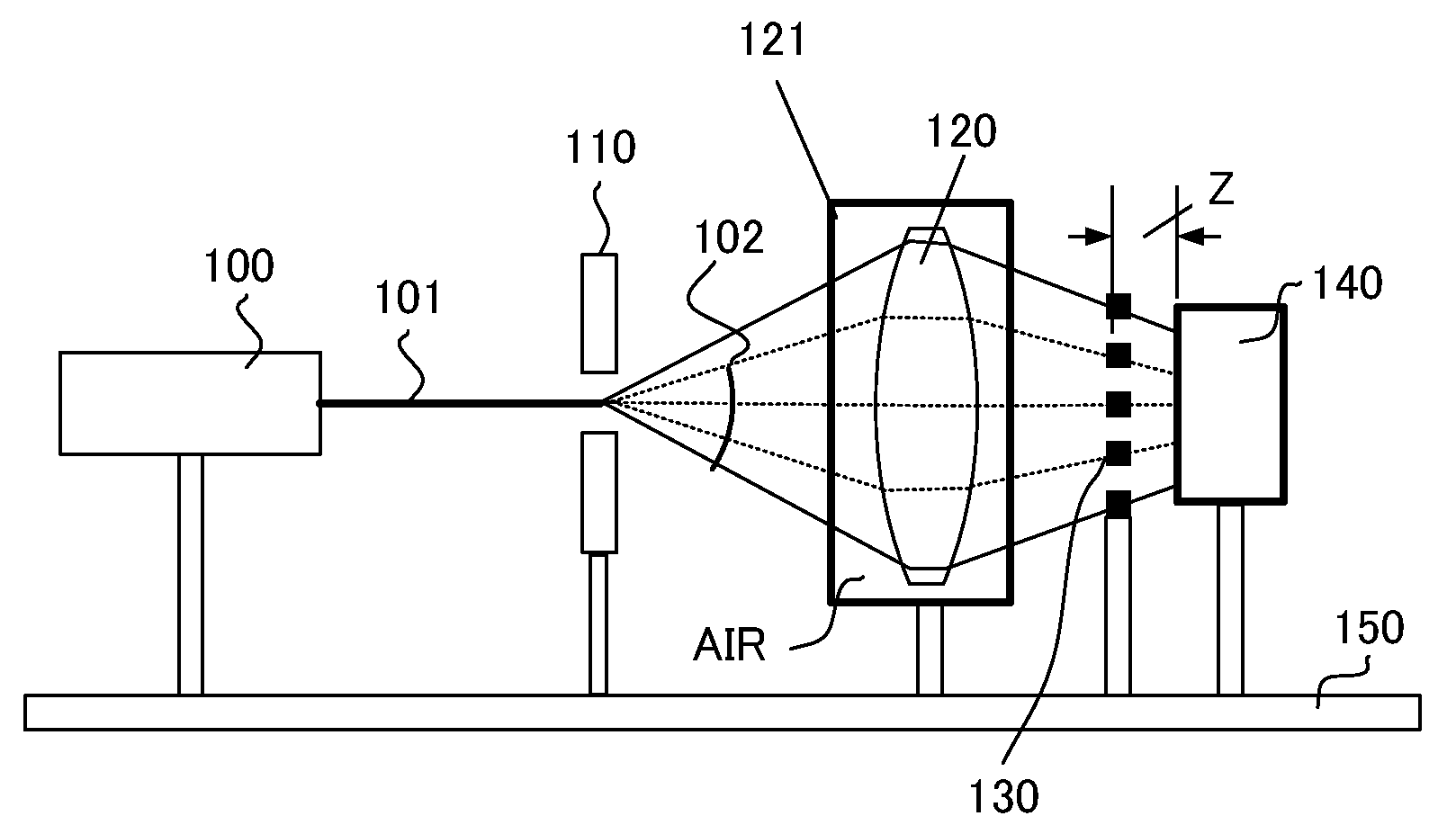
[0024]FIG. 1 shows a schematic configuration of a Talbot interferometer (refractive index distribution measurement apparatus) which is used when the test object is measured in the air (first medium). The test object 120 that is an optical element such as a lens is immersed in the air in a test object case 121. A refractive index of the air is lower than that of the test object 120 by 0.01 or more.
[0025]Laser light 101 emitted from a laser light source (e.g., He—Ne laser) 100 is diffracted when it passes through a pinhole (optical unit) 110. The diffracted light (reference light) 102 diffracted by the pinhole 110 passes through the air in the test object case 121, and enters and pass...
second embodiment
[0068]The second embodiment of the present invention discusses a test object 120 having a negative power and a measurement apparatus other than a shearing interferometer. FIG. 6 is a conceptual view of a measurement apparatus of this embodiment.
[0069]A pinhole 110 generates (reference) light having an ideal spherical wave by using laser light emitted from a laser light source 100. This light is converted into converged light by an illumination optical system 600. The converged light passes through the test object 120 that is a meniscus lens, and its transmission wavefront is measured by a Shack-Hartman sensor 610 that is a wavefront measurement sensor. As shown in FIG. 7, the Shack-Hartmann sensor 610 includes a lens array 611 and a CCD 612.
[0070]As the illumination optical system 600 is moved on a rail 150 in an optical axis direction of the test object 120, a light flux made incident upon the test object 120 can be turned into any one of a divergent light flux, a parallel light fl...
third embodiment
[0075]A measurement result of a refractive index distribution measurement method according to the present invention can be fed back to a method for manufacturing an optical element such as a lens.
[0076]FIG. 8 is an illustrative manufacturing flow of an optical element that uses molding.
[0077]In FIG. 8, S101 denotes a step of designing an optical element, and a designer designs an optical element by using optical designing software or the like. S102 denotes a step of designing and working a mold configured to mold the optical element based on the optical element designed in the step S101. S103 denotes a step of molding the optical element by using the mold worked in the step S102.
[0078]S104 denotes a step of measuring a shape of the optical element molded in the step S103 and of evaluating its accuracy. If the shape evaluated in the step S104 does not meet the accuracy requirement, a correction amount of a mirror surface of the mold is calculated in a step S105. The mold is worked ag...
PUM
| Property | Measurement | Unit |
|---|---|---|
| refractive index | aaaaa | aaaaa |
| refractive indices | aaaaa | aaaaa |
| refractive index distribution | aaaaa | aaaaa |
Abstract
Description
Claims
Application Information
 - R&D
- Intellectual Property
- Life Sciences
- Materials
- Tech Scout
- Unparalleled Data Quality
- Higher Quality Content
- 60% Fewer Hallucinations
Browse by: Latest US Patents, China's latest patents, Technical Efficacy Thesaurus, Application Domain, Technology Topic, Popular Technical Reports.
© 2025 PatSnap. All rights reserved.Legal|Privacy policy|Modern Slavery Act Transparency Statement|Sitemap|About US| Contact US: help@patsnap.com


