Microstructural polarized light-guide device

a technology of light-guide device and micro-structural polarization, which is applied in the direction of polarising elements, lighting and heating apparatus, instruments, etc., can solve the problem of not being able to expect light-us

Inactive Publication Date: 2010-07-01
NATIONAL TSING HUA UNIVERSITY
View PDF1 Cites 66 Cited by
  • Summary
  • Abstract
  • Description
  • Claims
  • Application Information

AI Technical Summary

Benefits of technology

[0010]In view of the aforementioned disadvantages and problems of the prior art, the primary objective of the present invention is to provide a microstructural polarized light-guide device, more particularly, a nano-scale light-guide device which is composed of a subw...

Problems solved by technology

So that the usage to ...

Method used


Image

  • Microstructural polarized light-guide device
  • Microstructural polarized light-guide device
  • Microstructural polarized light-guide device

Examples


Embodiment Construction

[0024]The present invention provides a microstructural polarized light-guide device, particularly, a nano-scale polarization beam splitter structure and a polarization conversion module; the light-guide device enables an unpolarized light to be transformed into a polarized light wave by using the microstructural polarization beam splitter structure and the polarization conversion module, therefore a polarized light wave is obtained with low absorption. The invention will become apparent in the following description taken in conjunction with the following drawings.

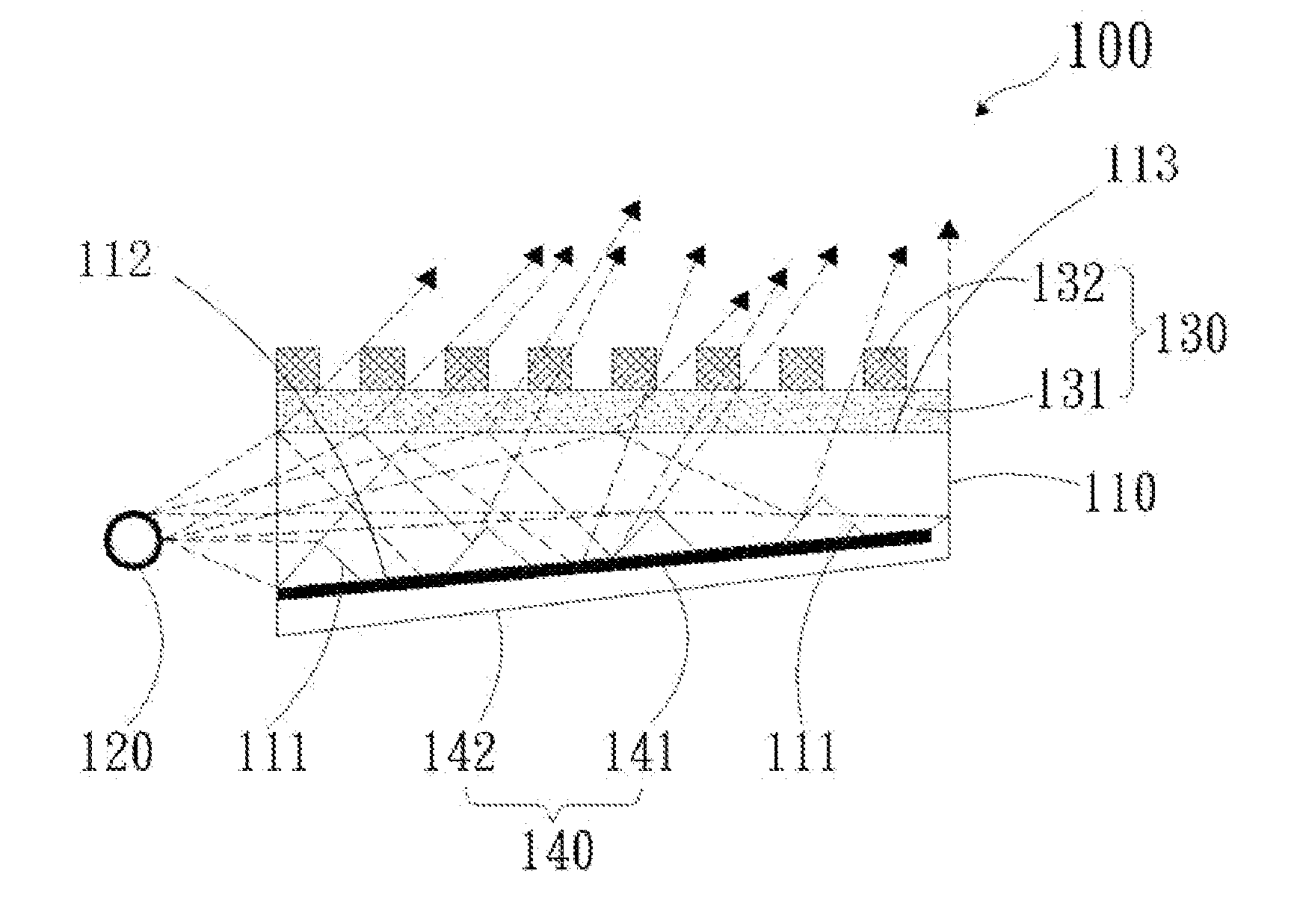
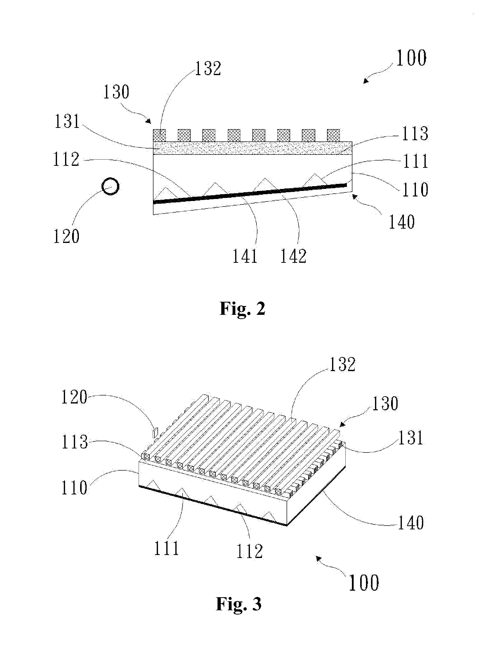
[0025]With reference to FIG. 2, a microstructural polarized light-guide device 100 comprises a light-guide plate 110, a CCFL 120, a polarization beam splitter structure 130 and a polarization conversion module 140.

[0026]The CCFL 120 is placed at the edge of the light-guide plate 110 and as the light source for the light-guide plate 110; in addition, the light source can be CCFL, LED or any other types of light emitting devi...


PUM


Abstract

A microstructural polarized light-guide device comprises an unpolarized light source module, a subwavelength polarization beam splitter structure and a polarization conversion module, the unpolarized light source module comprises a light-guide plate and a light source at the edge of the light-guide plate, the material of the light-guide plate is PMMA with the characteristic of high transparency, the surface of the light-guide plate has a plurality of extraction patterns, the polarization beam splitter structure is a nano-scale structure and comprises a dielectric nanograting layer and a metallic nanograting layer, and the dielectric nanograting layer and the metallic nanograting layer are vertically stacked with each other, the dielectric nanograting layer is integrated with a surface opposite to the surface with the plurality of extraction patterns, the polarization conversion module is disposed on the surface with the plurality of extraction patterns of the light-guide plate.

Description

BACKGROUND OF THE INVENTION[0001]1. Field of the Invention[0002]The present invention generally relates to a microstructural polarized light-guide device, more particularly, a nano-scale light-guide device which is composed of subwavelength polarization beam splitter structure, polarization conversion module, and light-guide module.[0003]2. Description of the Prior Art[0004]With reference to FIG. 1, which illustrates a side view showing a conventional back light structure. As shown in the figure, a back light module 1 mainly comprises an incident CCFL (cold cathode fluorescent lamp) 10, a reflection shade 9, a light-guide plate 7, a reflection plate 5, a diffusion plate 11, a prism plate 12A, a prism plate 12B, and an absorbing polarizer 13. Light emitted by the CCFL 10 or reflected by the reflection shade 9 may directly or indirectly enter into the light-guide plate 7 for propagation. Light passing through an optical-designed structure located at the lower portion of the light-guid...

Claims


Application Information

Patent Timeline
IPC IPC(8): F21V9/14F21V8/00
CPCF21V9/14G02B6/005G02B6/0056
Inventor CHEN, CHENG-HUANSUNG, CHENG-KUOCHEN, CHIEN-CHUANCHEN, CHIA-MENG
Owner NATIONAL TSING HUA UNIVERSITY
Why Eureka
Try Eureka