Turbine rotor blade tips that discourage cross-flow

a technology of turbine blades and tips, applied in the direction of liquid fuel engines, marine propulsion, vessels, etc., can solve the problems of insufficient leakage reduction, difficult cooling of airfoil tips, and limited strategy

Inactive Publication Date: 2010-07-01
GENERAL ELECTRIC CO
View PDF5 Cites 11 Cited by
  • Summary
  • Abstract
  • Description
  • Claims
  • Application Information

AI Technical Summary

Benefits of technology

[0006]The present application thus describes a turbine rotor blade for a gas turbine engine including an airfoil and dovetail for mounting the airfoil along a radial axis to a rotor disk inboard of a turbine shroud, the airfoil comprising: a pressure sidewall and a suction sidewall that join together at a leading edge and a trailing edge, the pressure sidewall and suction sidewall extending from a root to a tip plate; a pressure tip wall that extends radially outwardly from the tip plate, traversing from the leading edge to the trailing edge such that the pressure tip wall resides approximately adjacent to the termination of the pressure sidewall; a suction tip wall that extends radially outwardly from the tip plate, traversing from the leading edge to the trailing edge such that the suction tip wall resides approximately adjacent to the termination of the suction sidewall; and one or more tip ribs that extend substantially between the pressure tip wall and the suction tip wall.

Problems solved by technology

Maximum efficiency of the engine is obtained by minimizing the tip clearance or gap such that leakage is prevented, but this strategy is limited somewhat by the different thermal and mechanical expansion and contraction rates between the rotor blades and the turbine shroud and the motivation to avoid an undesirable scenario of having the tip rub against the shroud during operation.
Nevertheless, airfoil tips are particularly difficult to cool since they are located directly adjacent to the turbine shroud and are heated by the hot combustion gases that flow through the tip gap.
Conventional blade tip designs, however, all have certain shortcomings, including a general failure to adequately reduce leakage and / or allow for efficient tip cooling that minimizes the use of efficiency-robbing compressor bypass air.

Method used


Image

  • Turbine rotor blade tips that discourage cross-flow
  • Turbine rotor blade tips that discourage cross-flow
  • Turbine rotor blade tips that discourage cross-flow

Examples


Embodiment Construction

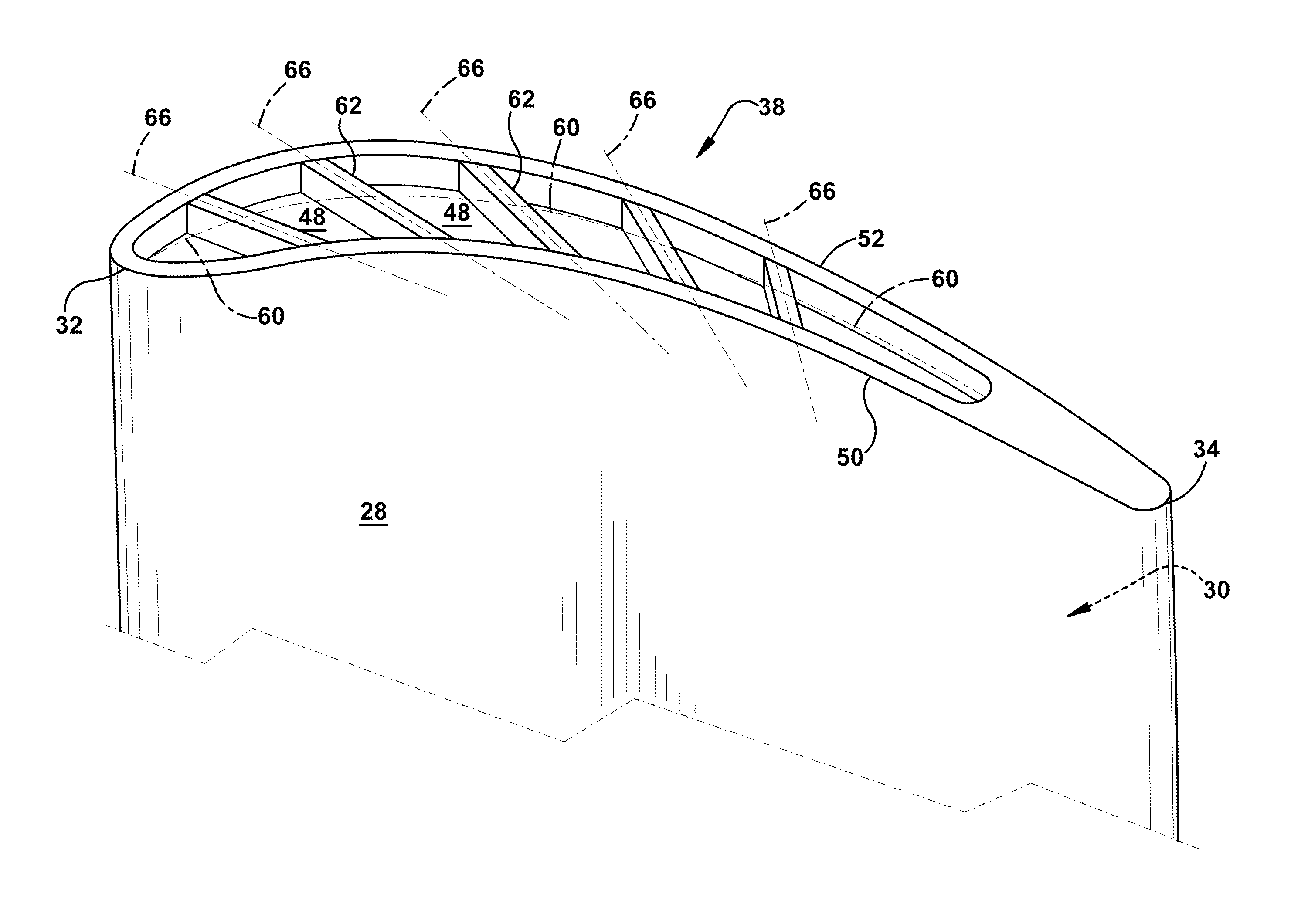
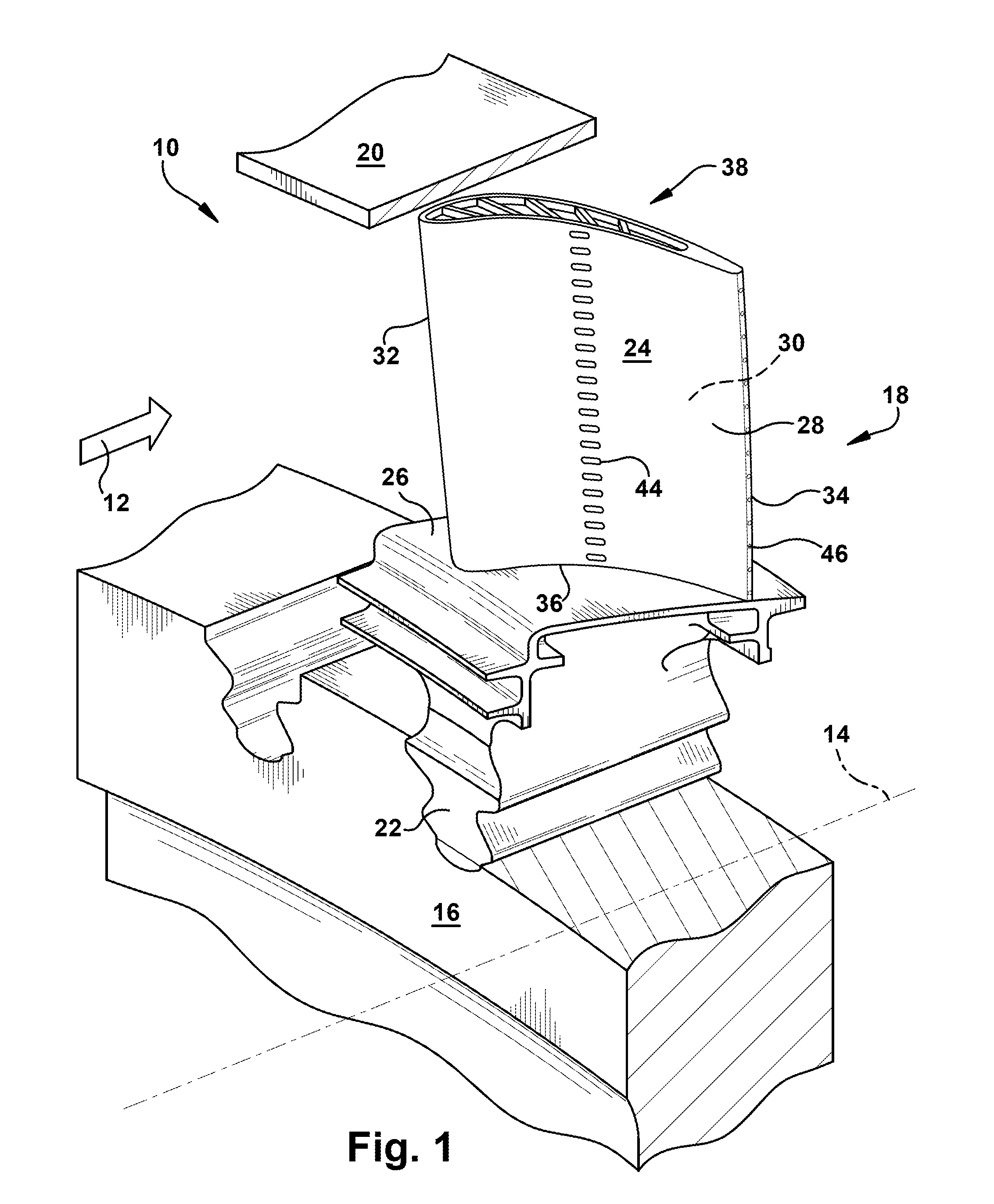
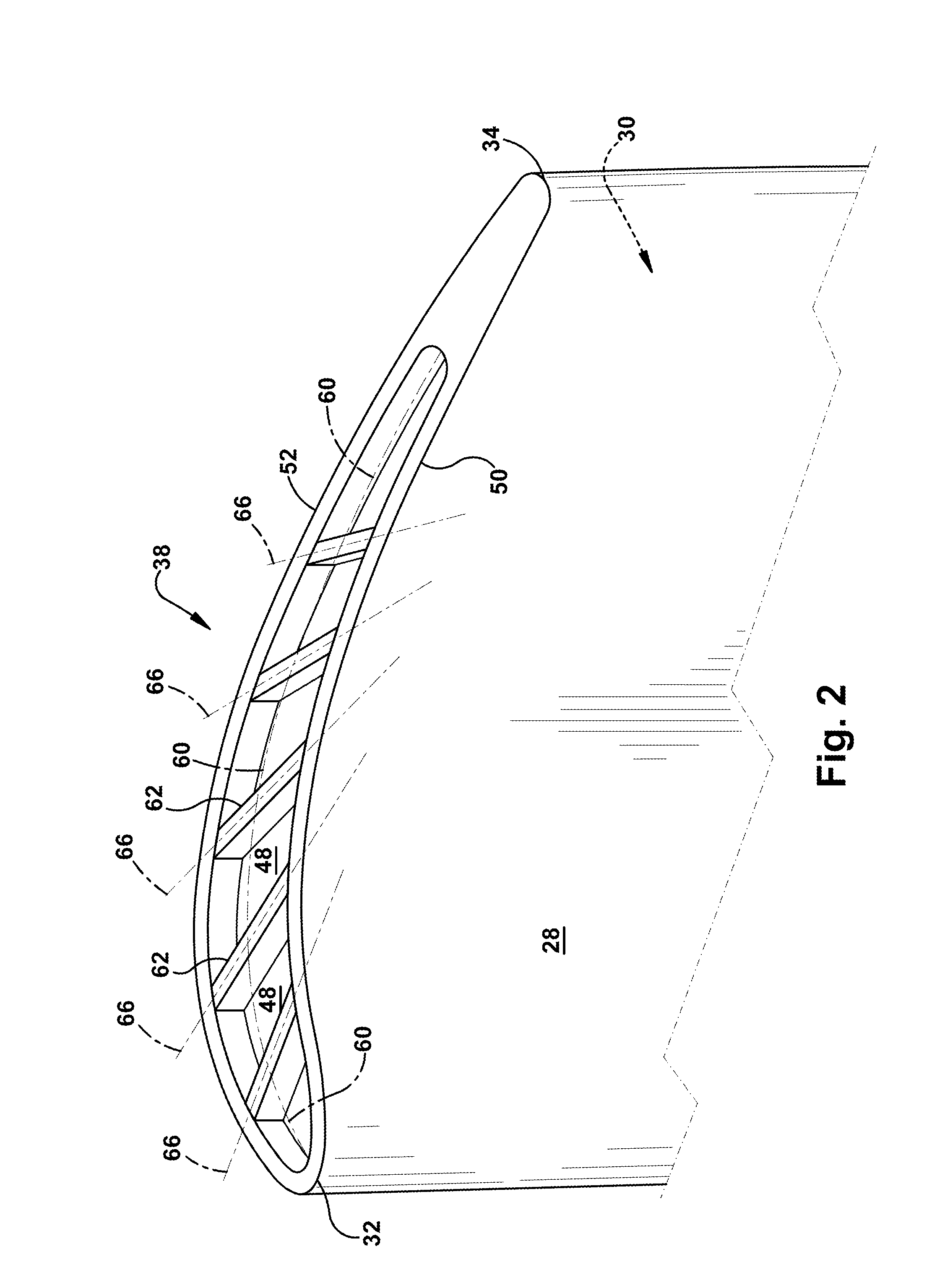
[0011]Referring now to the drawings, wherein identical numerals indicate the same elements throughout the figures, FIG. 1 depicts a portion of a turbine 10 of a gas turbine engine. The turbine 10 is mounted directly downstream from a combustor (not shown) for receiving hot combustion gases 12 therefrom. The turbine 10, which is axisymmetrical about an axial centerline axis 14, includes a rotor disk 16 and a plurality of circumferentially spaced apart turbine rotor blades 18 (one of which is shown) extending radially outwardly from the rotor disk 16 along a radial axis. An annular turbine shroud 20 is suitably joined to a stationary stator casing (not shown) and surrounds blades 18 for providing a relatively small clearance or gap therebetween for limiting leakage of combustion gases 12 therethrough during operation.

[0012]Each blade 18 generally includes a dovetail 22 which may have any conventional form, such as an axial dovetail configured for being mounted in a corresponding dovet...


PUM


Abstract

A turbine rotor blade for a gas turbine engine including an airfoil and dovetail for mounting the airfoil along a radial axis to a rotor disk inboard of a turbine shroud, the airfoil comprising: a pressure sidewall and a suction sidewall that join together at a leading edge and a trailing edge, the pressure sidewall and suction sidewall extending from a root to a tip plate; a pressure tip wall that extends radially outwardly from the tip plate, traversing from the leading edge to the trailing edge such that the pressure tip wall resides approximately adjacent to the termination of the pressure sidewall; a suction tip wall that extends radially outwardly from the tip plate, traversing from the leading edge to the trailing edge such that the suction tip wall resides approximately adjacent to the termination of the suction sidewall; and one or more tip ribs that extend substantially between the pressure tip wall and the suction tip wall.

Description

BACKGROUND OF THE INVENTION[0001]The present application relates generally to apparatus, methods and / or systems for discouraging cross-flow over turbine airfoil tips. More specifically, but not by way of limitation, the present application relates to apparatus, methods and / or systems related to turbine blade tips that include a squealer tip and / or cross ridges or ribs that discourage cross-flow the blade.[0002]In a gas turbine engine, it is well known that air is pressurized in a compressor and used to combust a fuel in a combustor to generate a flow of hot combustion gases, whereupon such gases flow downstream through one or more turbines so that energy can be extracted therefrom. In accordance with such a turbine, generally, rows of circumferentially spaced rotor blades extend radially outwardly from a supporting rotor disk. Each blade typically includes a dovetail that permits assembly and disassembly of the blade in a corresponding dovetail slot in the rotor disk, as well as an ...

Claims


Application Information

Patent Timeline
Patent Type & Authority Applications(United States)
IPC IPC(8): F01D5/28F01D5/30F01D5/14
CPCF01D5/20F01D5/18F01D25/12
Inventor HATMAN, ANCA
Owner GENERAL ELECTRIC CO
Why Eureka
Try Eureka