Endoscope Flexible Tube and Endoscope Device
a flexible tube and endoscope technology, applied in the field of endoscope flexible tubes, can solve the problems of unnecessarily excessive load on the body cavity, the second bending portion being stuck with the acutely flexed body cavity, and the difficulty of insertion portion to be inserted into the flexed portion
- Summary
- Abstract
- Description
- Claims
- Application Information
AI Technical Summary
Benefits of technology
Problems solved by technology
Method used
Image

Examples
first embodiment
[0047]The first embodiment of the present invention will be explained referring to the drawings.
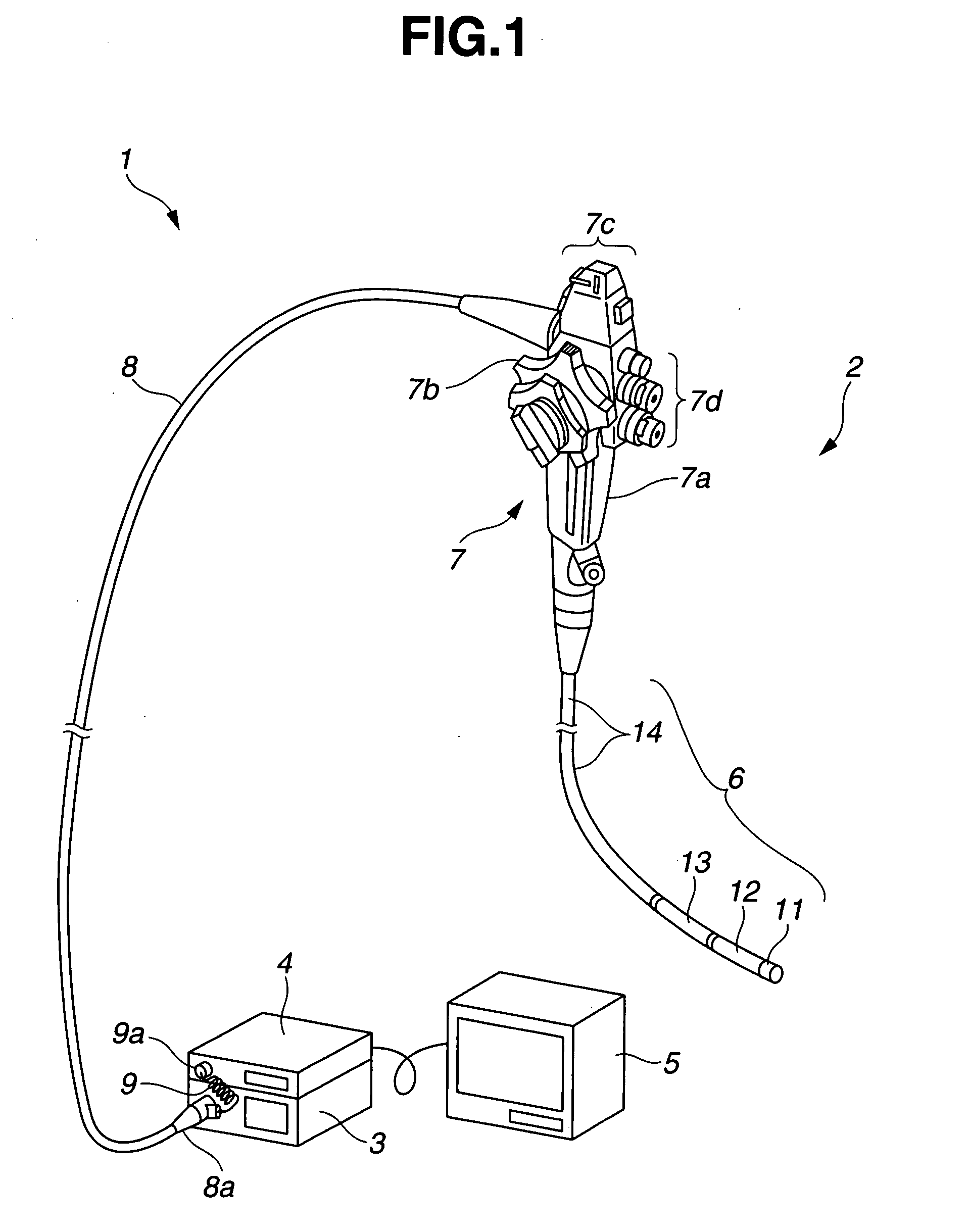
[0048]FIG. 1 is a view showing an entire configuration of an endoscope device with an endoscope.
[0049]Referring to FIG. 1, an endoscope device 1 includes an electronic endoscope equipped with not shown image pickup means (hereinafter referred to an endoscope) 2, a light source device 3 for supplying illumination light, a processor 4 for generating a video signal based on an electric signal transmitted from the image pickup means of the endoscope 2, and a monitor 5 as a display unit for displaying an endoscopic image in response to the video signal.
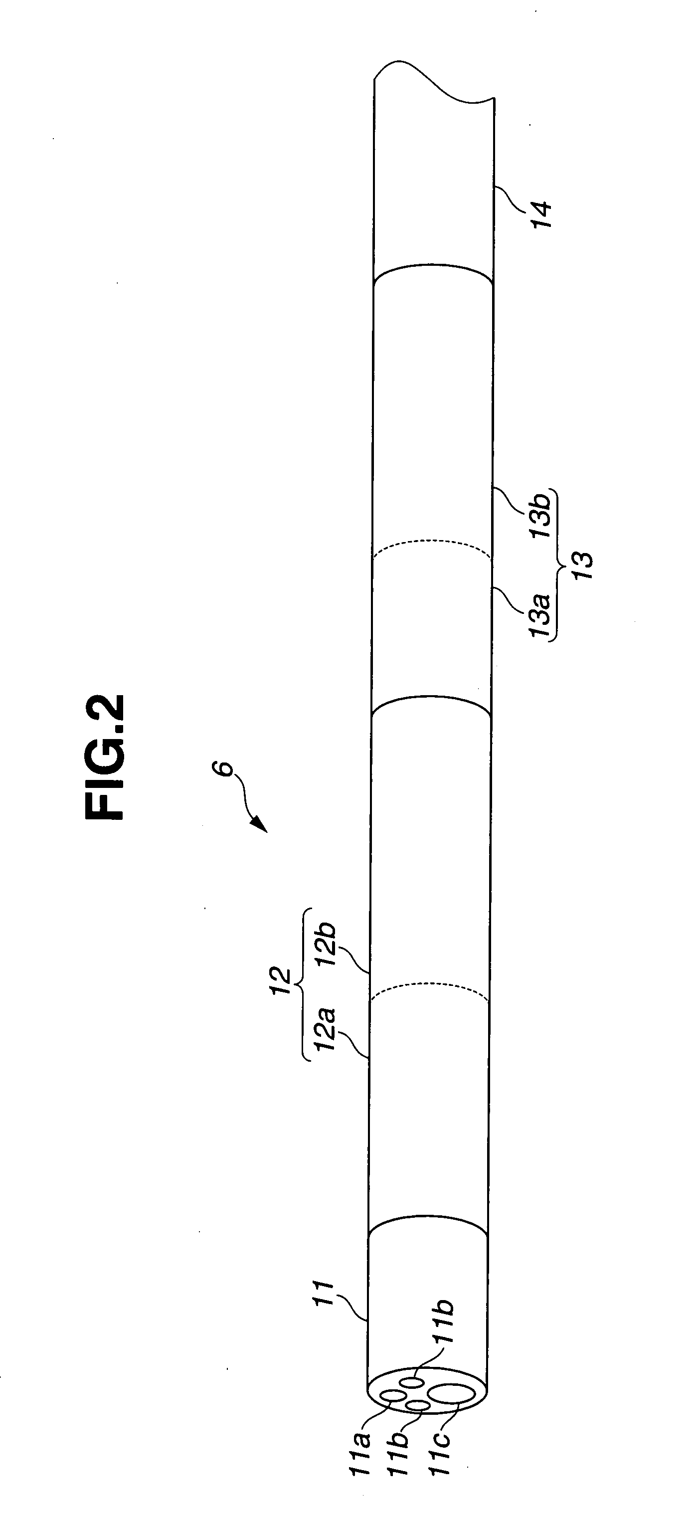
[0050]The endoscope 2 according to the embodiment mainly includes an insertion portion 6 as an endoscope flexible tube which is long enough to be inserted into the body cavity, an operation portion 7 positioned at the proximal end side of the insertion portion 6, and a universal cord 8 which extends from one side portion of the operation portion...
second embodiment
[0150]A second embodiment according to the present invention will be described referring to the drawings.
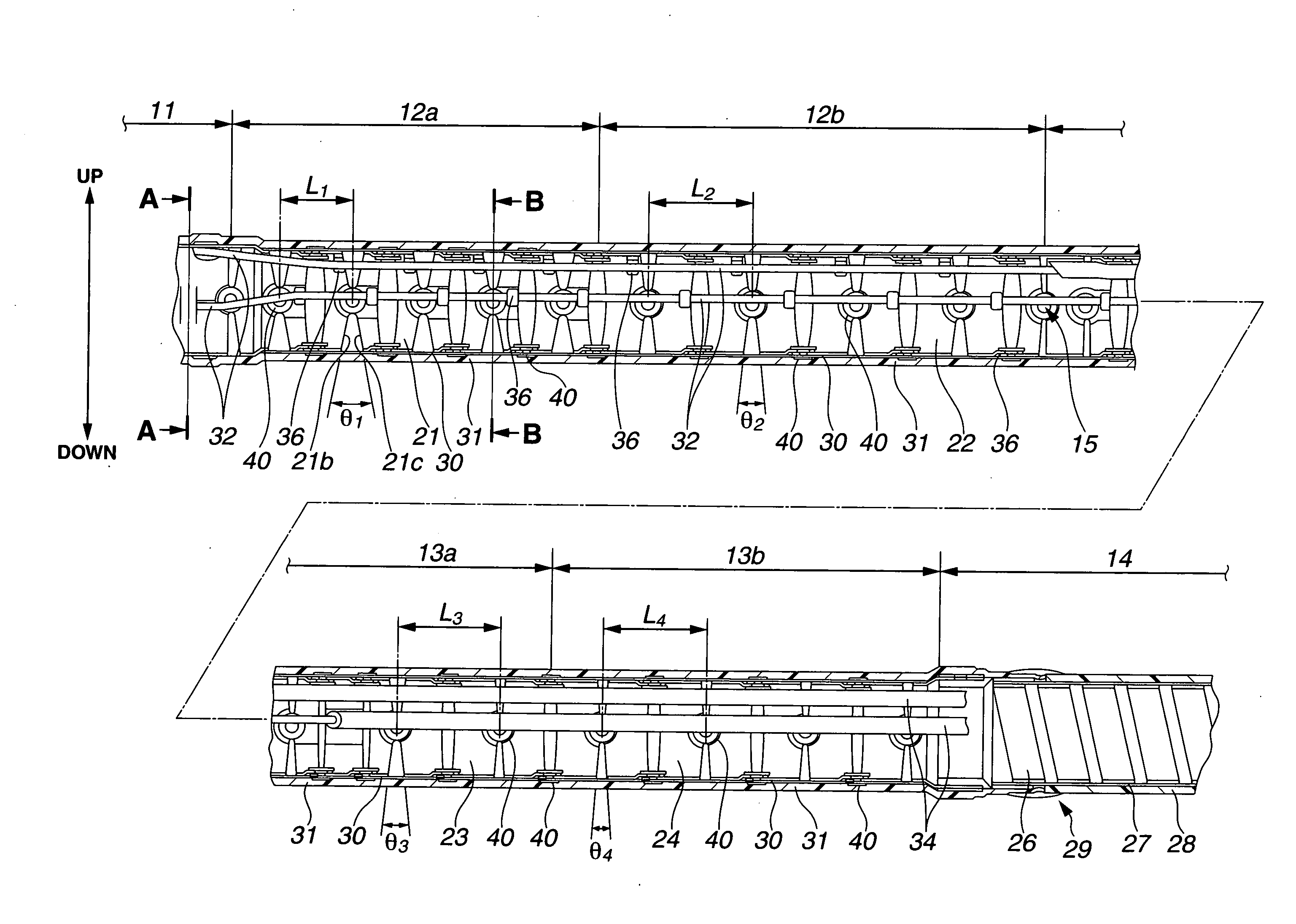
[0151]FIG. 18 is a sectional view showing the section of the distal end portion of the insertion portion 6, which has been cut in the longitudinal direction. FIG. 19 is a sectional view of the insertion portion taken along line C-C shown in FIG. 18. FIG. 20 is a sectional view of the first curvature transition portion of the insertion portion taken along line D-D shown in FIG. 18. In the embodiment, the configuration, functions and effects of the endoscope which are the same as those of the endoscope that has been already described in the first embodiment will be designated with the same codes, and the explanations thereof, thus, will be omitted. The explanation with respect only to the different configuration, functions and the effects will be made hereinafter.
[0152]Referring to FIG. 18, besides the four bending operation wires 32 for bending operation of the bending portion 12 ...
third embodiment
[0160]A third embodiment according to the present invention will be described referring to the drawings.
[0161]FIG. 21 is a sectional view showing the section of the distal end portion of the insertion portion 6, which has been cut in the longitudinal direction. FIG. 22 is a sectional view of the curvature transition portion in substantially the linear state, which has been cut in the longitudinal direction. FIG. 23 is a sectional view of the curvature transition portion in the maximum bent state, which has been cut in the longitudinal direction.
[0162]In the description of the embodiment, the configuration, functions and effects which are the same as those described in the first and the second embodiments will be designated as the same codes, and explanation thereof, thus, will be omitted. The different configuration, functions and effects will only be described hereinafter.
[0163]Referring to FIG. 21, a curvature regulation tube 50 as a flex tube where the belt-like member is helical...
PUM
 Abstract
Description
Claims
Application Information
 - R&D
- Intellectual Property
- Life Sciences
- Materials
- Tech Scout
- Unparalleled Data Quality
- Higher Quality Content
- 60% Fewer Hallucinations
Browse by: Latest US Patents, China's latest patents, Technical Efficacy Thesaurus, Application Domain, Technology Topic, Popular Technical Reports.
© 2025 PatSnap. All rights reserved.Legal|Privacy policy|Modern Slavery Act Transparency Statement|Sitemap|About US| Contact US: help@patsnap.com