
Patient's skin puncturing device

Active Publication Date: 2010-07-01
HTL STREFA SPOLKA Z O O
View PDF3 Cites 6 Cited by
  • Summary
  • Abstract
  • Description
  • Claims
  • Application Information

AI Technical Summary

Benefits of technology

[0006]The purpose of the present invention is to provide a disposable patient's skin puncturing device for collecting blood sample for diagnostic purposes, which is cheap, safe, both for the patient and for the service personnel and easy in use.
[0007]Particularly, the purpose of this invention is to provide the patient's skin puncturing device with the structure which enables to reduce a pain being felt by the patient during the skin puncture and to retract very quickly the puncturing needle tip from the skin after puncture for enhancing a comfort of puncturing device application.
[0008]The next purpose of this invention is to provide the patient's skin puncturing device of the structure which enables to eliminate unfavourable effect of the multiple skin puncture present in the known puncturing devices in the puncture phase as well as in the retraction phase of the piston with the puncturing needle or other puncturing assembly into the inside of the housing, whereas this effect is caused by rebounding the puncturing assembly from the drive and return springs at least one end of which is free.

Problems solved by technology

Thus, the wings get broken and a subsequent re-use of the device is not possible.
These impacts induce unfavourable dynamic drive spring tensions and cause that the puncture assembly, quick-retracting under the influence of the return spring, bounces from the expanded drive spring.
In the known puncturing devices, it is observed a disadvantageous effect of multiple skin puncture as a consequence of series of successive rebounds of the puncturing assembly from the drive spring.
The rebounds accompany with the puncturing device vibrations which are adverse for the user's and / or patient's feelings.

Method used


Image

  • Patient's skin puncturing device
  • Patient's skin puncturing device
  • Patient's skin puncturing device

Examples


Embodiment Construction

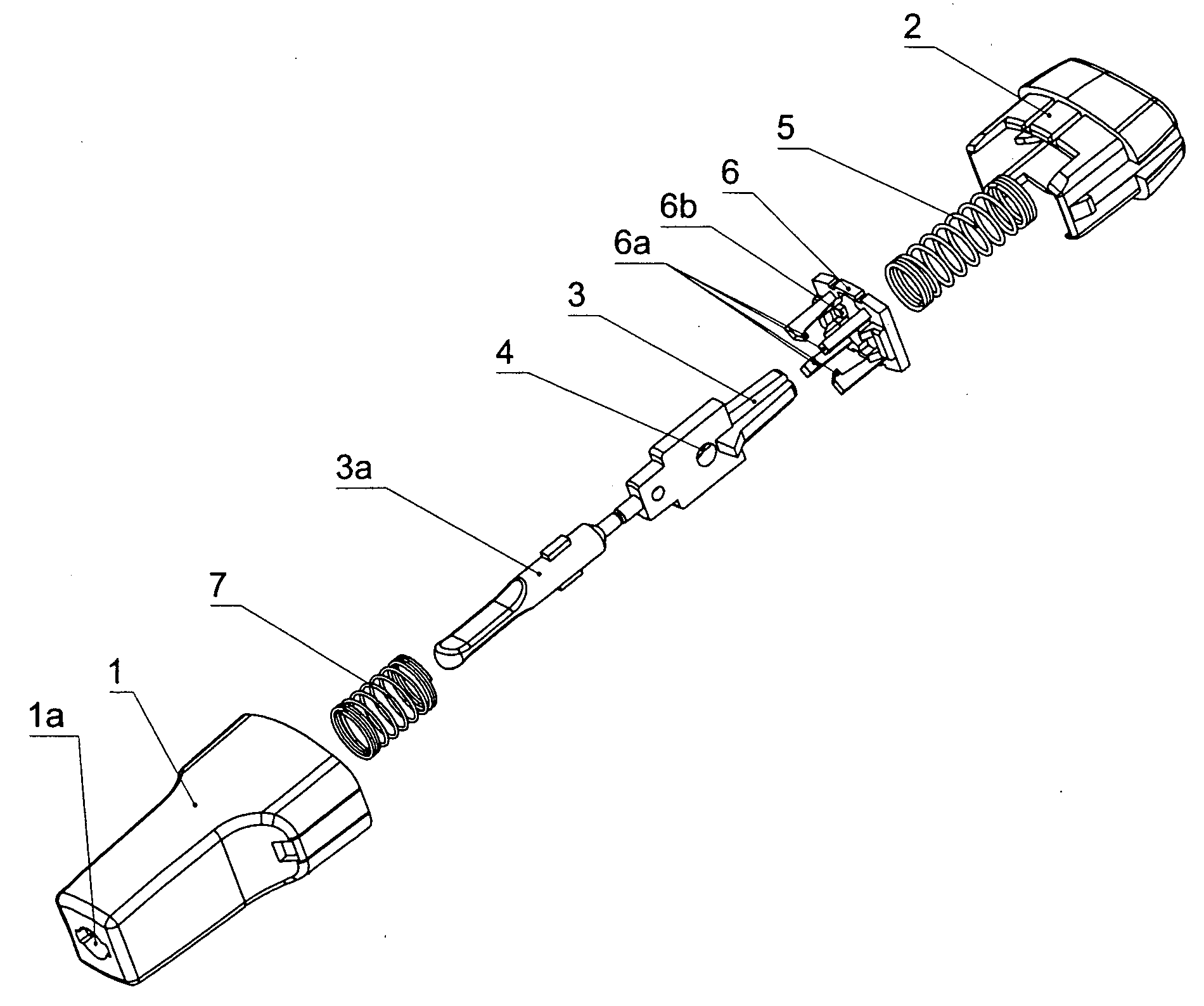
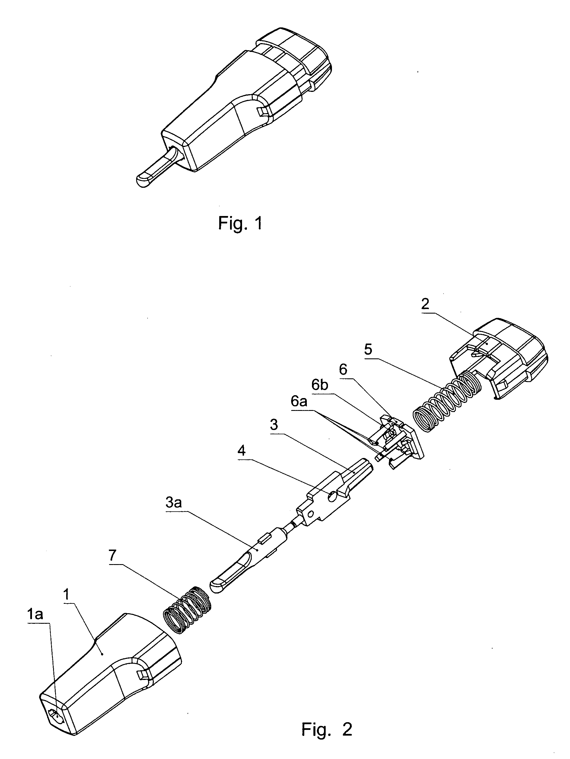
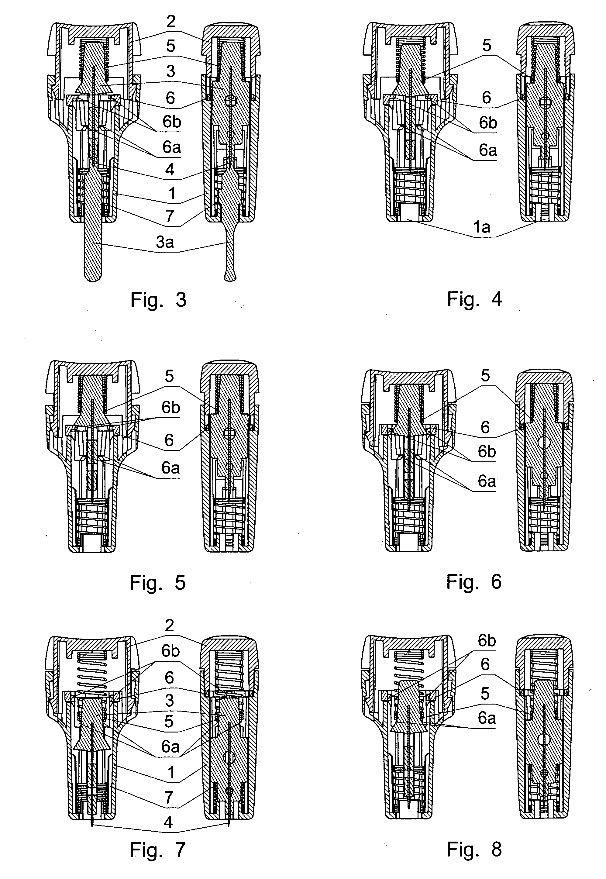
[0019]The patient's skin puncturing device according to the one of the preferred embodiments of the invention, as shown in the drawings, is comprised of a housing 1 and a push button 2 mounted on the one of ends of the housing 1. The other end of the housing 1 has an opening la for a puncturing needle 4. In the housing 1 a lancet is positioned, which is longitudinally movable. The lancet has a body 3 in which the puncturing needle 4 is seated. The puncturing needle 4 has a tip protected by a sheath 3a which is removed before use of the device. A drive spring 5 is arranged between the lancet body 3 and the internal side of the face end of the push button 2. A return spring 7 is placed inside the housing 1 between the lancet body 3 and the other end of the housing 1, in which the opening la is made for the puncturing needle 4. In the housing 1, between the drive spring 5 and the lancet a washer 6 is placed. The washer 6 comprises lancet actuation locking means in the form of interlock...


PUM


Abstract

A patient's skin puncturing device, particularly for collecting a blood sample for diagnostic purposes, comprises a housing (1), a lancet slidably positioned inside the housing (1) and having a body (3) with a sheathed puncturing needle (4) seated therein, and a push button (2) positioned at the one end of the housing (1). Between a face end of the push button (2) and the lancet body (3) a drive spring (5) is placed, and between the other end of the housing (1), which is provided with an opening (Ia) for the puncturing needle (4), and the lancet body (3) a return spring (7) is placed. Between the housing (1) and the lancet body (3) is placed lancet actuation locking means, preferably in the form of interlocks (6b) of a washer (6). The device has drive spring catching means, preferably in the form of grabs (6a) of the washer (6), to preclude the drive spring (5) from following the lancet in the puncture phase and in the retraction phase of the lancet.

Description

TECHNICAL FIELD[0001]The subject of the invention is a patient's skin puncturing device, particularly for collecting blood samples for diagnostic purposes.BACKGROUND ART[0002]From the patent specification No. U.S. Pat. No. 5,356,420 the puncturing device is known comprising a sleeve and a push button positioned at one sleeve end. The other sleeve end terminates with a bottom with an opening therein. Inside the sleeve a piston is slidably positioned, terminating with a push rod at the end closer to the push button, and with a puncturing needle at the end closer to the bottom opening. Inside the sleeve, between the push button face and the piston a drive spring is located, and between the piston and the sleeve bottom a return spring is placed. The piston comprises locking means of an actuation of the piston with the puncturing needle, which is located on an outer perimeter of the piston and is in the form of wings resting on an internal projection of the sleeve. When the device is use...

Claims


Application Information

Patent Timeline
IPC IPC(8): A61B5/151A61B17/34
CPCA61B5/150022A61B5/150152A61B5/150412A61B5/150503A61B5/150549A61B5/150618A61B5/150717A61B5/150916A61B5/150923A61B5/15111A61B5/15117A61B5/1513A61B5/15144A61B5/151
Inventor KARBOWNICZEK, JACEKSARNA, WOJCIECHJANKOWSKI, ANDRZEJWYSZOGRODZKI, WOJCIECHCZERNECKI, ANDRZEJ
Owner HTL STREFA SPOLKA Z O O
Learn More