Oral Prosthesis System Including an Electrostimulation Device Associated with a Wireless Transmission-Reception Device

Inactive Publication Date: 2010-07-01
UNIV JOSEPH FOURIER
View PDF6 Cites 5 Cited by
  • Summary
  • Abstract
  • Description
  • Claims
  • Application Information

AI Technical Summary

Benefits of technology

[0017]According to an embodiment, the microcontrollers are microcontrollers of very low average curre

Problems solved by technology

In practice, the building of such devices com

Method used


Image

  • Oral Prosthesis System Including an Electrostimulation Device Associated with a Wireless Transmission-Reception Device
  • Oral Prosthesis System Including an Electrostimulation Device Associated with a Wireless Transmission-Reception Device

Examples


Embodiment Construction

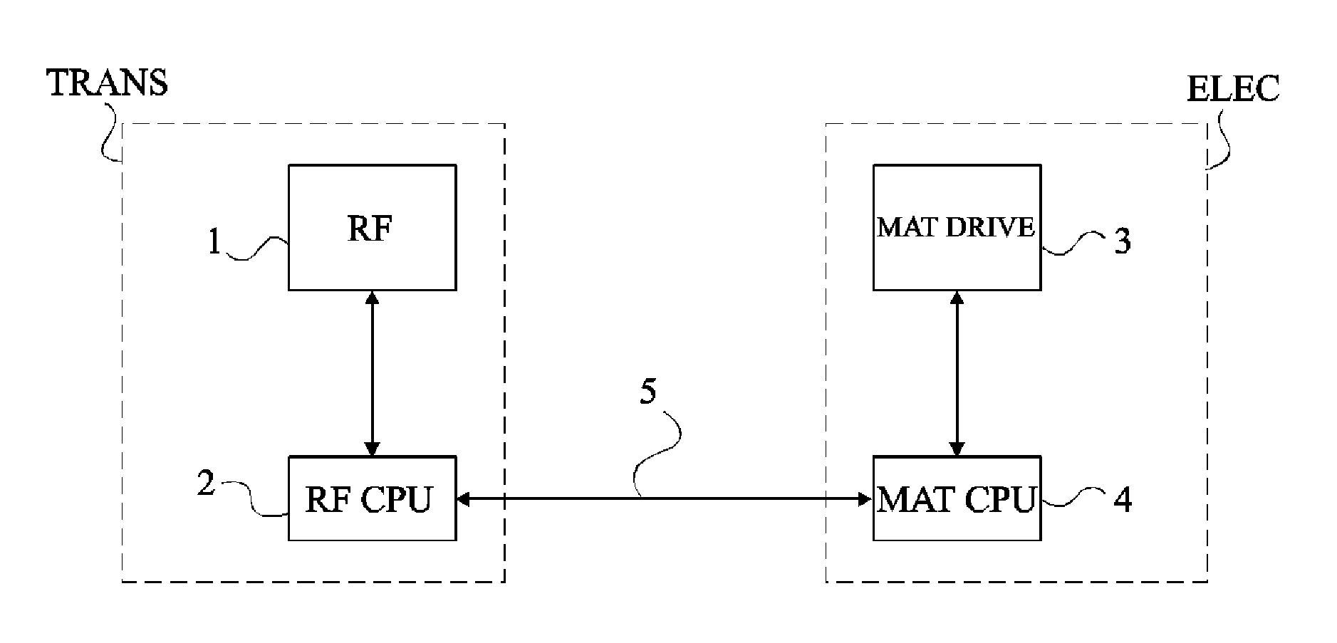
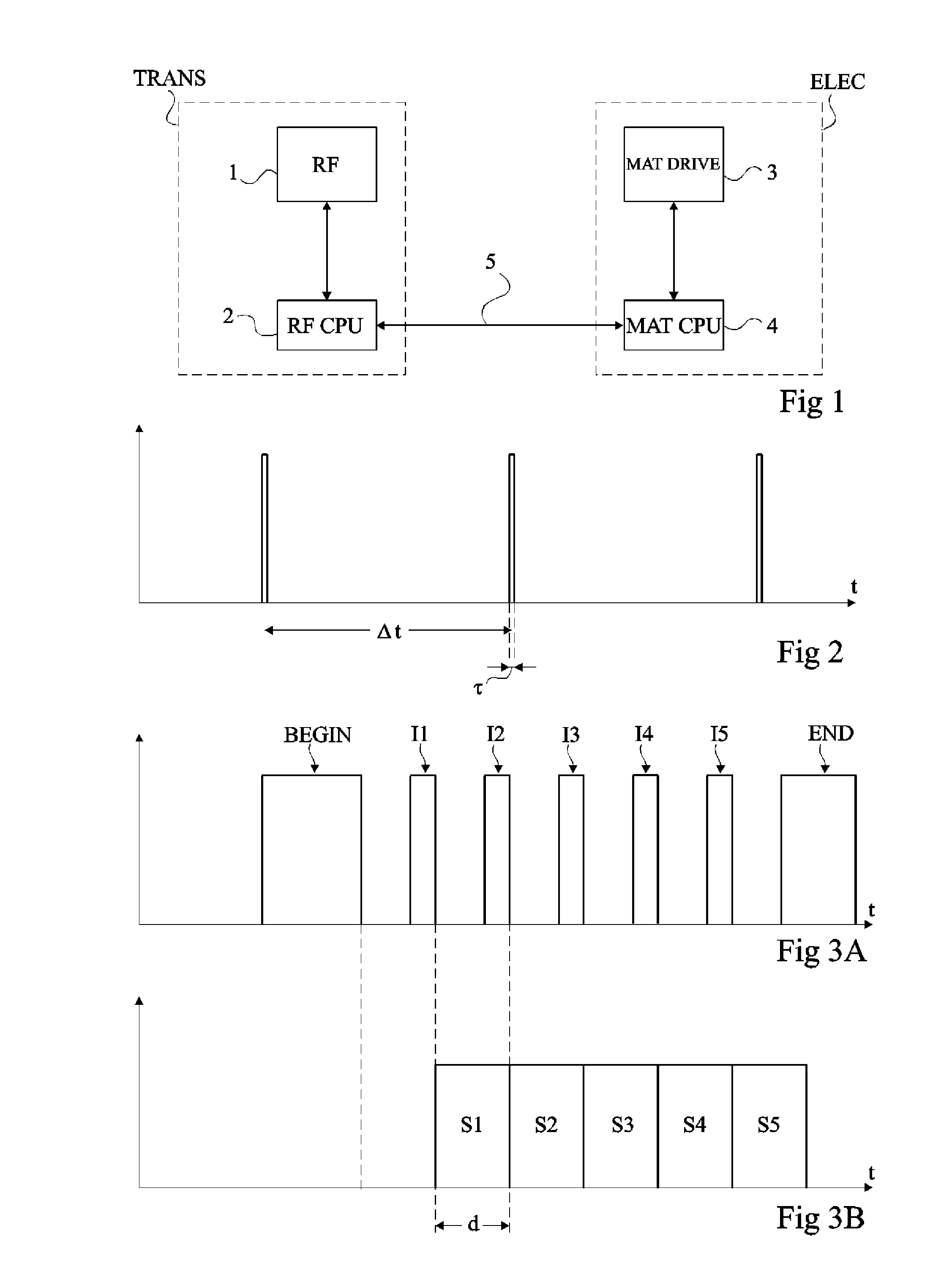
[0024]FIG. 1 illustrates a simplified diagram of an oral prosthesis system comprising an electrical tongue stimulation unit associated with a wireless transceiver device according to an embodiment of the present invention.

[0025]The system according to an embodiment of the present invention comprises a transceiver block TRANS comprising a radio frequency transceiver RF 1 associated with a processor RFCPU 2 dedicated to transmit / receive operations. The system also comprises an electrical stimulation block comprising an array of electrodes associated with elements for controlling electrical stimulation array MATDRIVE 3 driven by a dedicated processor MATCPU 4. Processors 2 and 4 are associated via a serial interface of universal asynchronous transceiver type (UART) 5.

[0026]Surprisingly, using two processors placed in the oral prosthesis provides a lower consumption than the use of a more powerful processor capable of managing transmit / receive operations as well as electrical stimulatio...


PUM


Abstract

An oral prosthesis system comprising an electrical tongue stimulation unit associated with a wireless transceiver device and comprising two microcontrollers, the first microcontroller dedicated to transmit and receive operations, and the second microcontroller dedicated to the control of an electrical stimulation array.

Description

FIELD OF THE INVENTION[0001]The present invention relates to the forming of electrical tongue stimulation units.DISCUSSION OF PRIOR ART[0002]Electrical stimulation units comprise an array of electrodes placed in an individual s hard palate above the tongue in the form of a removable oral prosthesis likely to be attached to the patient s dentition. Such a unit is for example described in U.S. Pat. No. 6,430,450.[0003]The use of electrical tongue stimulation units has been suggested for many applications. Such applications especially aim at increasing a permanently or temporarily disabled person s autonomy by compensating for a temporary or permanent disability. Such units are especially capable of providing the patient with information that his or her body does not give him or her. These applications comprise a rehabilitation after a trauma of a joint or of a body segment due to accidental causes, to a disease, or to surgery.[0004]Such applications are made possible since the patient...

Claims


Application Information

Patent Timeline
IPC IPC(8): A61N1/36A61N1/08
CPCA61B5/682A61F9/08A61N1/36014G06F1/3203A61N1/36007A61N1/36103A61N1/36167A61N1/36034
Inventor COLIN, BRUNOPAYAN, YOHAN
Owner UNIV JOSEPH FOURIER
Why Eureka
Try Eureka