
Path Planning Device, Path Planning Method, and Computer Program

a path planning and path technology, applied in the direction of programme control, distance measurement, printers, etc., can solve the problems of difficult to obtain the optimal solution from infinite paths, difficult to calculate efficiently a stable motion path, and not the optimal solution

Inactive Publication Date: 2010-07-01
SONY CORP
View PDF15 Cites 95 Cited by
  • Summary
  • Abstract
  • Description
  • Claims
  • Application Information

AI Technical Summary

Benefits of technology

[0021]It is also desirable to provide a path planning device, a path planning method, and a computer program, which can search for a path of a control target for avoiding an obstruction and correct the path into a smooth path for easy use in motion control or path control of the control target.
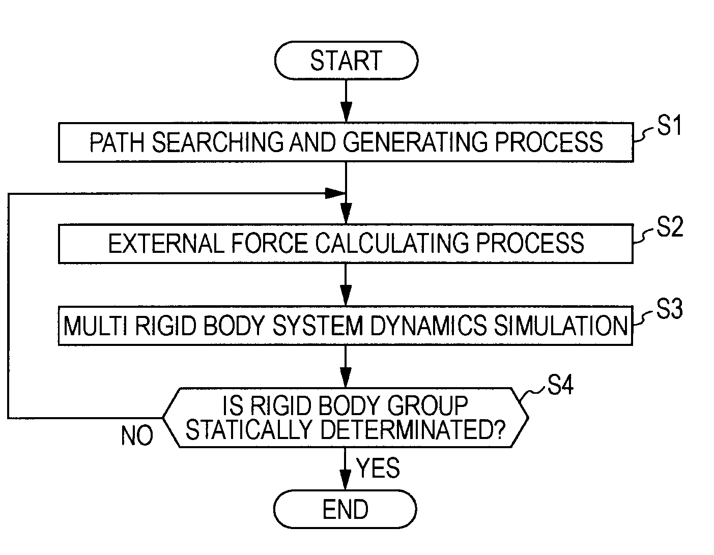
[0043]According to the embodiments of the invention, it is possible to satisfy the requirement “to avoid the infiltration between objects in a position and posture path” by the use of the dynamical restriction expression that the replulsive force corresponding to the shortest distance between the control target and the obstruction is made to act on the rigid bodies.

Problems solved by technology

(1) to acquire rapidly an initial position and posture path for accomplishing a target position and posture path, which is not the optimal solution;
(2) to acquire a smooth position and posture path;
(3) to avoid infiltration (collision or interference) between objects in a position and posture path; and
(4) to approach an ideal position and posture path (reflecting a designer's intention) as closely as possible.
It is difficult to acquire the optimal solution from infinite paths.
In the potential method, it is difficult to calculate efficiently a stable motion path, in that there is a possibility that plural positions and postures having the minimum potential may appear in addition to the target position and posture, which is very intuitive.
The stochastic road map method has a disadvantage in that it is difficult to plan a motion in a narrow space surrounded with many obstructions, that is, plural positions and postures should be sampled.
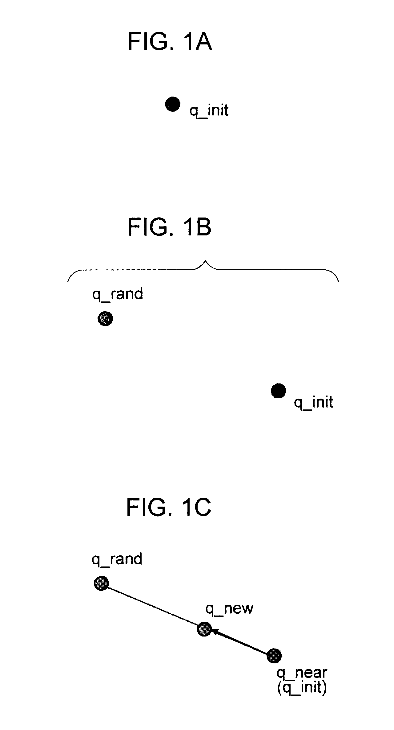
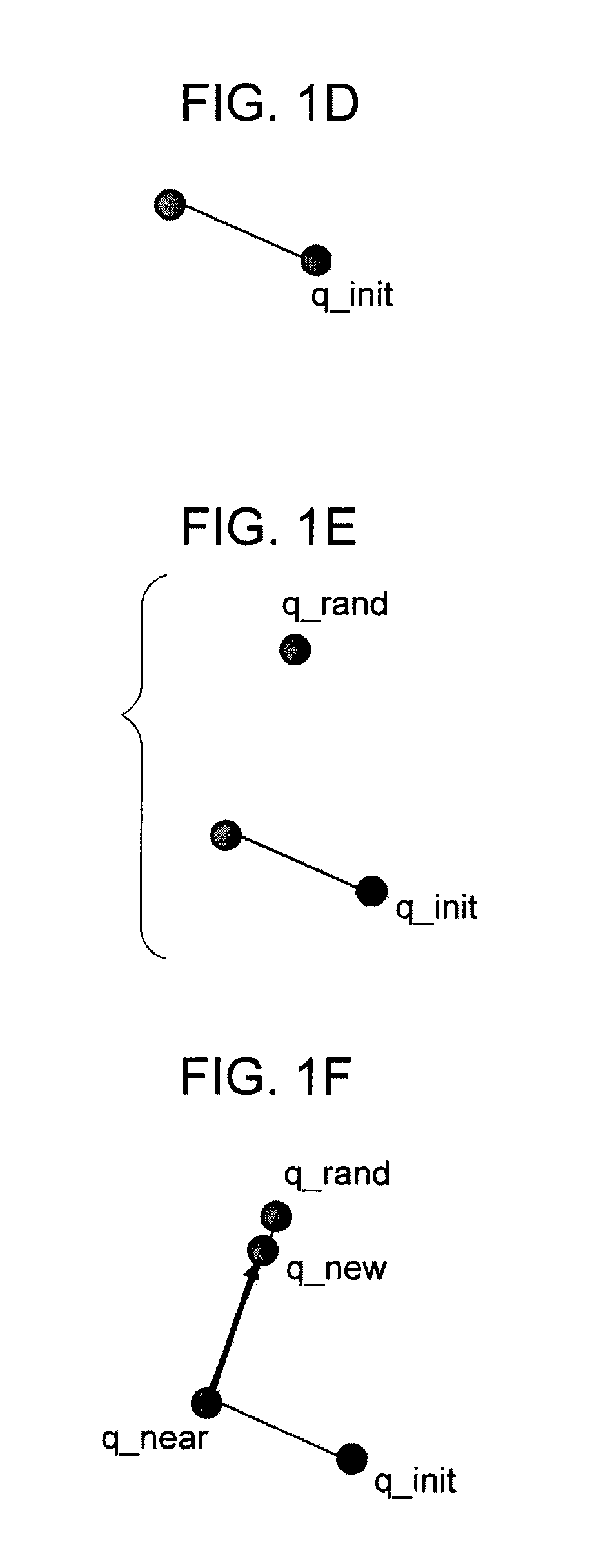
The RRT algorithm, can enable relatively rapid path planning in a multi-dimensional configuration space, but has a disadvantage that the searched path includes many detours due to the use of random search.
However, no method can satisfy the requirements of (2) to acquire a smooth position and posture path, (3) to avoid infiltration between objects, and (4) to approach an ideal position and posture path.
In other words, it is not possible to obtain a satisfactory path for use in the motion control of a robot or the final control for the path planning of a finger tip of a multi-joint arm.
In this method, the correction of path can be carried out using positions in a space and three-degree-of-freedom postures, but there is a problem in that the calculation amount is excessively great.

Method used


Image

  • Path Planning Device, Path Planning Method, and Computer Program
  • Path Planning Device, Path Planning Method, and Computer Program
  • Path Planning Device, Path Planning Method, and Computer Program

Examples


Embodiment Construction

[0077]Hereinafter, embodiments of the invention will be described in detail with reference to the accompanying drawings.

[0078]To generate rapidly a smooth path of a robot or a multi-joint arm from the present position and posture to the target position and posture, the following four requirements should be satisfied. In the following description, a “control target” includes a robot or a multi-joint arm.

[0079](1) To acquire rapidly an initial position and posture path for accomplishing a target position and posture path, which is not the optimal solution.

[0080](2) To acquire a smooth position and posture path.

[0081](3) To avoid infiltration (collision or interference) between objects in a position and posture path.

[0082](4) To approach an ideal position and posture path (reflecting a designer's intention) as closely as possible.

[0083]To satisfy the requirement of (1), how to search rapidly and satisfactorily for a path for accomplishing the minimum purpose not necessarily restricted ...


PUM


Abstract

A path planning device includes: an initial position and posture path acquiring unit which acquires an initial position and posture path including a plurality of nodes connecting present position and posture of a control target to target position and posture and which configures a rigid body corresponding to the control target in each node in the position and posture path; an interference detector which detects interference with the control target by an obstruction; an external force calculator which calculates an external force for each rigid body; and a multi rigid body system dynamics simulation unit which performs a multi rigid body system dynamics simulation on a plurality of equations of rigid body motion and which acquires positions and postures of the control target at times corresponding to the nodes in the position and posture path.

Description

BACKGROUND OF THE INVENTION[0001]1. Field of the Invention[0002]The present invention relates to a path planning device, a path planning method, and a computer program, which can plan a motion control of a robot or a motion route or path of a control target such as a finger tip of a multi-joint arm from present position and posture to target position and posture in a motion space, and more particularly, to a path planning device, a path planning method, and a computer program, which can correct a path of a control target for avoiding an obstruction into a smooth path for easy use in motion control or path control.[0003]2. Description of the Related Art[0004]For example, when a moving machine such as a robot or a finger tip as an end effector of a multi-joint arm is autonomously controlled in motion, a motion route or path from some position and posture (present position and posture: start) to another position and posture (target position and posture: goal) in a motion space should b...

Claims


Application Information

Patent Timeline
IPC IPC(8): G06F19/00B25J9/22G05B19/4155G05D1/02
CPCB25J9/1666
Inventor NAGANO, MASAKUNI
Owner SONY CORP
Learn More