Signal compression method and apparatus

a signal compression and signal technology, applied in the field of audio compression, can solve the problems of low compression efficiency of a lossless coder and low quality of reconstructed speech signals of a lossy coder, and achieve the effect of improving the compression efficiency of a lossless coder and the quality, and simple operations

Active Publication Date: 2010-07-01
HUAWEI TECH CO LTD
View PDF7 Cites 24 Cited by
  • Summary
  • Abstract
  • Description
  • Claims
  • Application Information

AI Technical Summary

Benefits of technology

[0029]In the technical solution under embodiments of the present disclosure, the autocorrelation coefficient correction factors are adjusted according to the original autocorrelation coefficients so that the adjusted autocorrelation coefficient correction factors can express the difference of input signals, thereby avoiding ill-conditioned cases of special input signals, making the modified autocorrelation coefficients more suitable for subsequent compression processing, improving the compression efficiency of a lossless coder and the quality of reconstructed speech signals of a lossy coder, and involving only simple operations.

Problems solved by technology

In the process of implementing the present disclosure, there are at least these defects in the prior art: because all signals are processed in the same way, ill-conditioned case may occur for some special input signals, and the solving of the autocorrelation matrix is instable, which leads to low compression efficiency of a lossless coder and low quality of reconstructed speech signals of a lossy coder.

Method used


Image

  • Signal compression method and apparatus
  • Signal compression method and apparatus
  • Signal compression method and apparatus

Examples


first embodiment

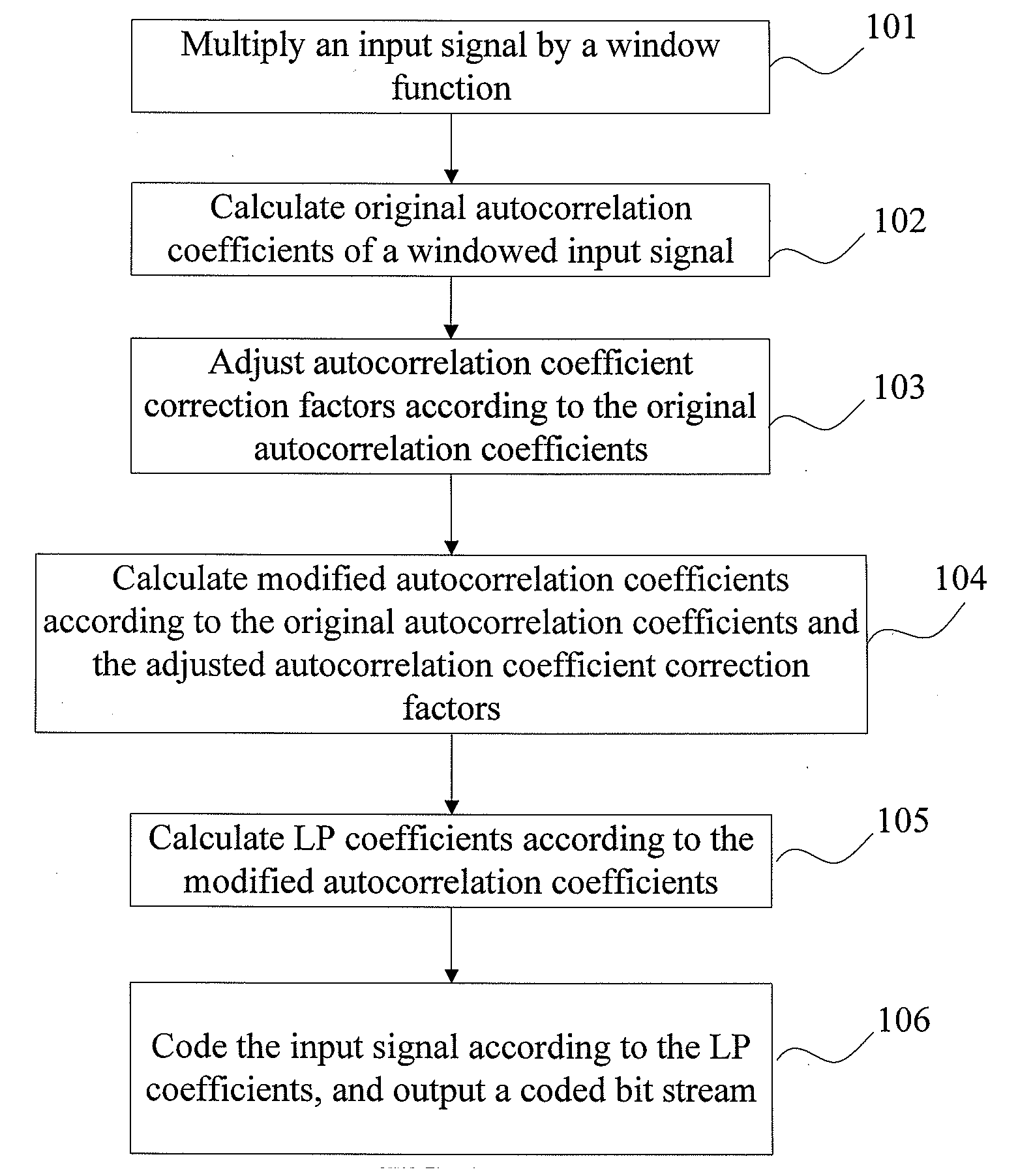
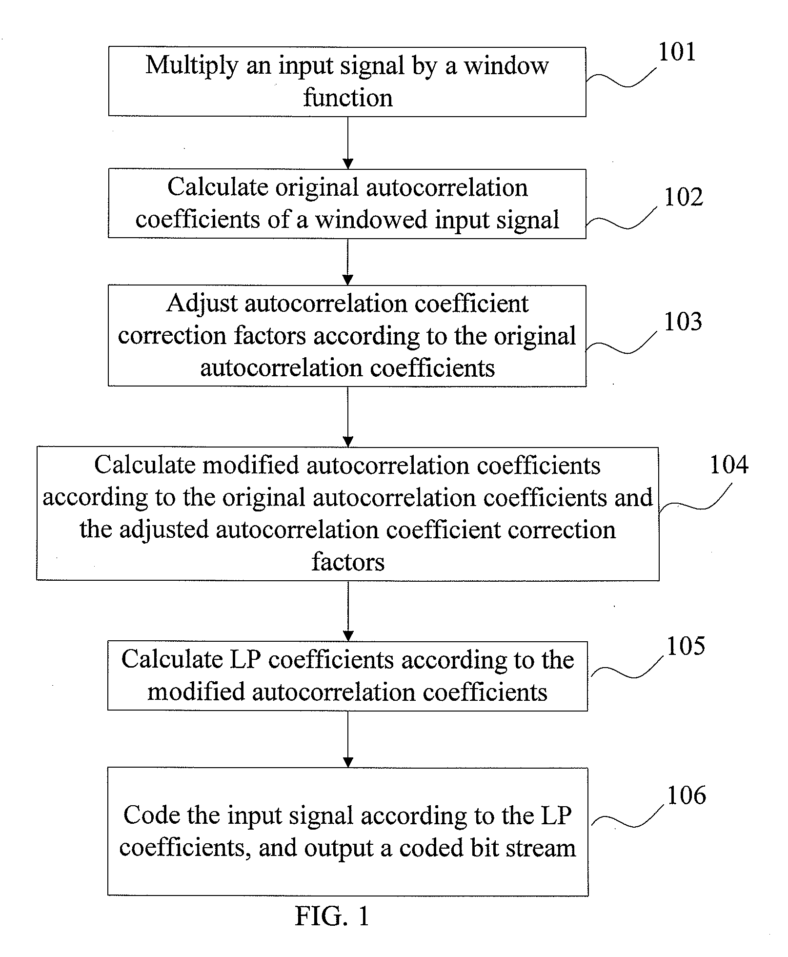
[0043]FIG. 1 is a flowchart of a signal compression method in the first embodiment of the present disclosure. The method includes the following steps:

[0044]Step 101: Multiply an input signal by a window function.

[0045]Step 102: Calculate original autocorrelation coefficients of a windowed input signal.

[0046]Step 103: Adjust autocorrelation coefficient correction factors according to the original autocorrelation coefficients.

[0047]Step 104: Calculate modified autocorrelation coefficients according to the original autocorrelation coefficients and the adjusted autocorrelation coefficient correction factors.

[0048]The autocorrelation coefficient correction factors include a white-noise correction factor and a lag-window. Adjusting the autocorrelation coefficient correction factors may be: adjusting the white-noise correction factor and the lag-window, or adjusting the white-noise correction factor only, or adjusting the lag-window only.

[0049]Adjusting the autocorrelation coefficient corr...

second embodiment

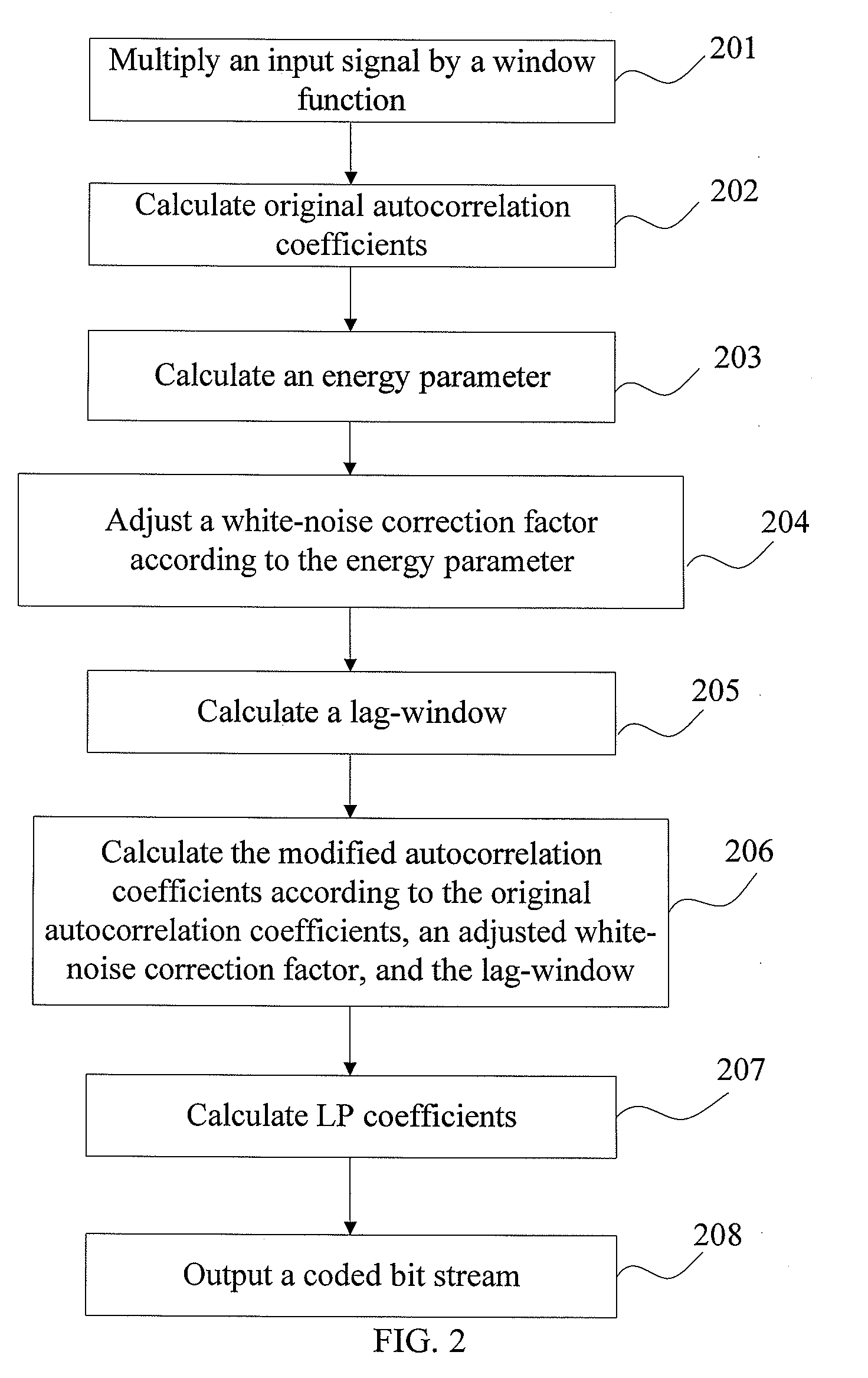
[0055]FIG. 2 is a flowchart of a signal compression method in the second embodiment of the present disclosure. The method includes the following steps:

[0056]Step 201: Multiply an input signal by a window function. The window here may be the window applied to lossy coding in the prior art. The input signal s(n) is multiplied by the window function win(n) to obtain a windowed input signal s′(n):

s′(n)=win(n)s(n) n=0, . . . N−1, where N is the frame length.

[0057]Step 202: Calculate original autocorrelation coefficients r(k) ac cording to the windowed input signal s′ (n), for example, through the following formula:

r(k)=∑n=kN-1s′(n)s′(n-k)

k=0, . . . p, where p is the order of LP.

[0058]Step 203: Calculate an energy parameter E according to the original autocorrelation coefficients.

[0059]In some embodiments, the frame average energy may be calculated according to the first coefficient r(0) of the original autocorrelation coefficients:

Ener_avg=r(0) / N, where N is the frame length.

[0060]In oth...

third embodiment

[0074]FIG. 3 is a flowchart of a signal compression method in the third embodiment of the present disclosure. The method includes the following steps:

[0075]Step 301: Multiply an input signal by a window function. The window here may be the window applied to lossy coding in the prior art. The input signal s(n) is multiplied by the window function win(n) to obtain a windowed input signal s′(n):

s′(n)=win(n)s(n) n=0, . . . N−1, where N is the frame length.

[0076]Step 302: Calculate the original autocorrelation coefficients r(k) according to the windowed input signal s′(n), for example, through the following formula:

r(k)=∑n=kN-1s′(n)s′(n-k)k=0,…,p,

[0077]where p is the order of LP.

[0078]Step 303: Determine a white-noise correction factor to be winlag(0)=1.0001.

[0079]Step 304: Calculate at least one reflection coefficient of the windowed input signal according to the original autocorrelation coefficients. In this embodiment, only the first reflection coefficient is calculated to simplify th...


PUM


Abstract

A signal compression method includes: multiplying an input signal by a window function, calculating original autocorrelation coefficients of a windowed input signal. The method also includes calculating a white-noise correction factor or a lag-window according to the original autocorrelation coefficients, and calculating modified autocorrelation coefficients according to the original autocorrelation coefficients, the white-noise correction factor and the lag-window. The method further includes calculating linear prediction coefficients according to the modified autocorrelation coefficients, and outputting a coded bit stream according to the linear prediction coefficients.

Description

CROSS-REFERENCE TO RELATED APPLICATIONS[0001]This application claims priority to Chinese Patent Application No. 200810247024.1, filed on Dec. 30, 2008, and Chinese Patent Application No. 200910149823.X, filed on Jun. 25, 2009, both of which are hereby incorporated by reference in their entireties.FIELD OF THE DISCLOSURE[0002]The present disclosure relates to audio compression, and in particular, to a signal compression method and apparatus.BACKGROUND OF THE DISCLOSURE[0003]To save the bandwidth for transmitting and storing speech and audio signals, the speech and audio coding technologies are applied widely. Currently, these coding technologies are mainly classified into lossy coding and lossless coding technologies.[0004]Linear prediction (LP) analysis is widely applied in lossless compression coding to reduce the dynamic range of input signals and to remove the redundancy of the near sample points of signals, but bandwidth expansion is not generally applied in lossless coding.[000...

Claims


Application Information

Patent Timeline
Patent Type & Authority Applications(United States)
IPC IPC(8): G10L19/00
CPCG10L19/06G10L19/008G10L19/04G10L19/12H03M7/30
Inventor QI, FENGYANMIAO, LEIXU, JIANFENGZHANG, DEJUNTADDEI, HERVE MARCELZHANG, QING
Owner HUAWEI TECH CO LTD
Why Eureka
Try Eureka