Thermal type flow sensor

a flow sensor and flow rate technology, applied in the direction of ohmic-resistance heating, liquid/fluent solid measurement, instruments, etc., can solve the problems of deterioration, error in the temperature difference control of the resistive element, and deterioration of flow rate measurement precision, so as to reduce at least one and maintain the effect of measurement precision

Active Publication Date: 2010-07-08
HITACHI ASTEMO LTD
View PDF8 Cites 13 Cited by
  • Summary
  • Abstract
  • Description
  • Claims
  • Application Information

AI Technical Summary

Benefits of technology

[0011]The present invention is to provide a thermal type flow sensor capable of reducing the thermal deterioration of the resistive element while maintaining the response of the sensor element, and maintaining the excellent measurement precision for a long period of time, or to provide a thermal type flow sensor capable of maintaining the measurement precision for a long period of time with a reduction in the influence of the stress that is applied to the sensor element.
[0015]On the contrary, the present invention senses the resistance change of the lower-side resistive element among the plural heat resistive elements and controls the current of the entire heat resistive elements. Therefore, it is possible to suppress the thermal deterioration of the relatively low heat resistive element for conducting the current control while the thermal value of the entire heat resistive elements is sufficiently ensured.(2) Also, the thermal type flow sensor having the following configuration is proposed.
[0025]In order to cope with the above problem, the resistive element and the electric terminal pad, which are formed on the substrate, are disposed at positions apart from each other on the substrate. Also, a thin-walled portion that reduces the transmission of the stress is formed between the resistive element and the electric terminal pad which are formed on the sensor element. Hereinafter, the specific embodiments of the above configuration will be described.
[0029]According to the above configuration, the thermal type flow sensor is capable of reducing at least one of the characteristic variation due to the deterioration of the heat resistive element due to the application of the stress, and of maintaining the measurement precision for a long period of time.

Problems solved by technology

As a generally trend, the heat resistive element become thermally deteriorated as the element is used, and is liable to be deteriorated as compared with the remaining resistive element.
The above phenomenon leads to an error in the temperature difference control of the resistive element and the deterioration of a precision in the flow rate measurement.
However, in the above configuration, because a thermal transmission delay from the heat resistive element to the temperature sensitive resistive element occurs, a response is delayed as much.
Also, because a reference power supply is used for a driver circuit, the sensor is affected by a fluctuation of the reference power supply.
The above resistance variation causes the deterioration of the measurement precision.

Method used


Image

  • Thermal type flow sensor
  • Thermal type flow sensor
  • Thermal type flow sensor

Examples


first embodiment

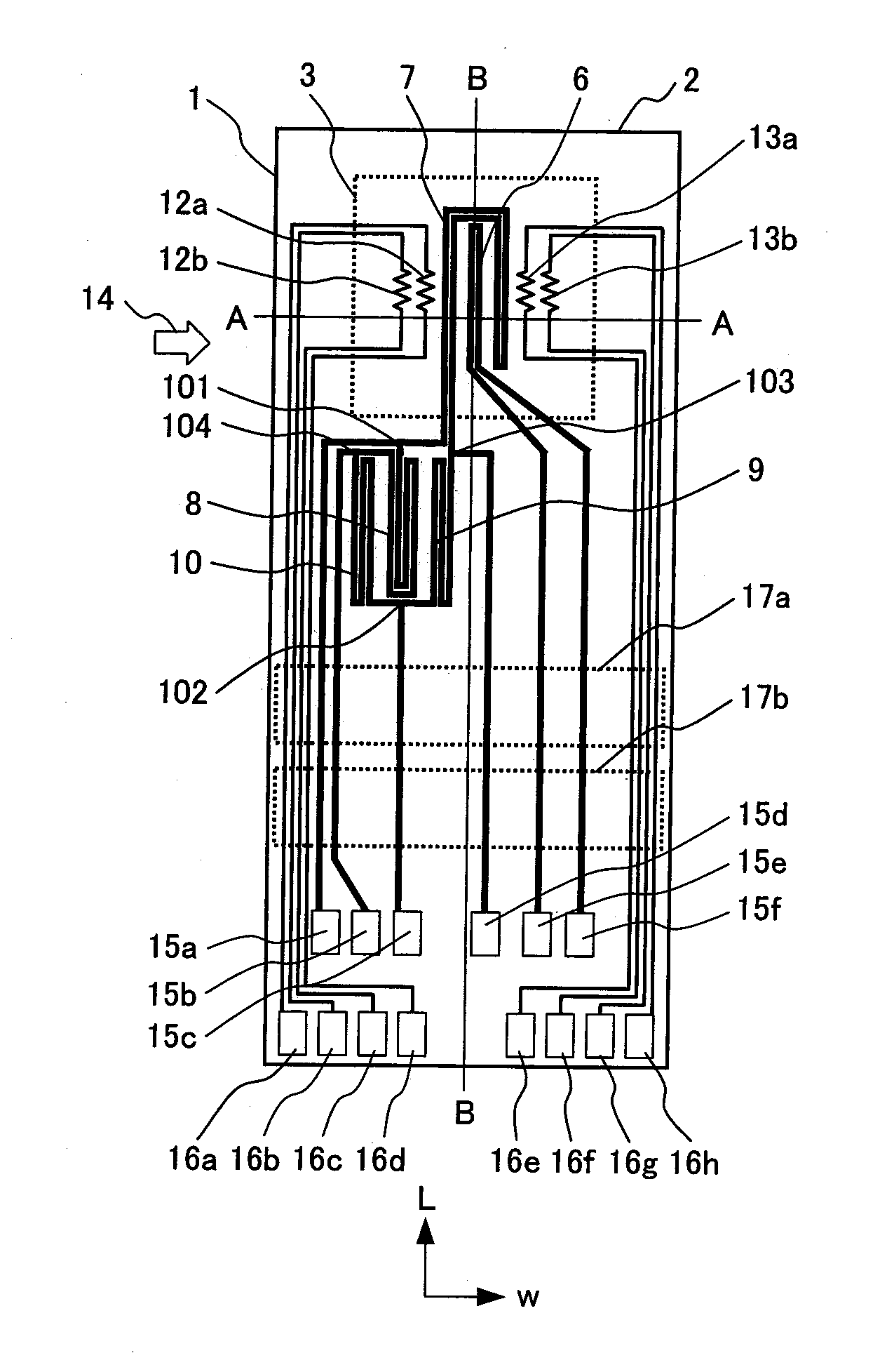
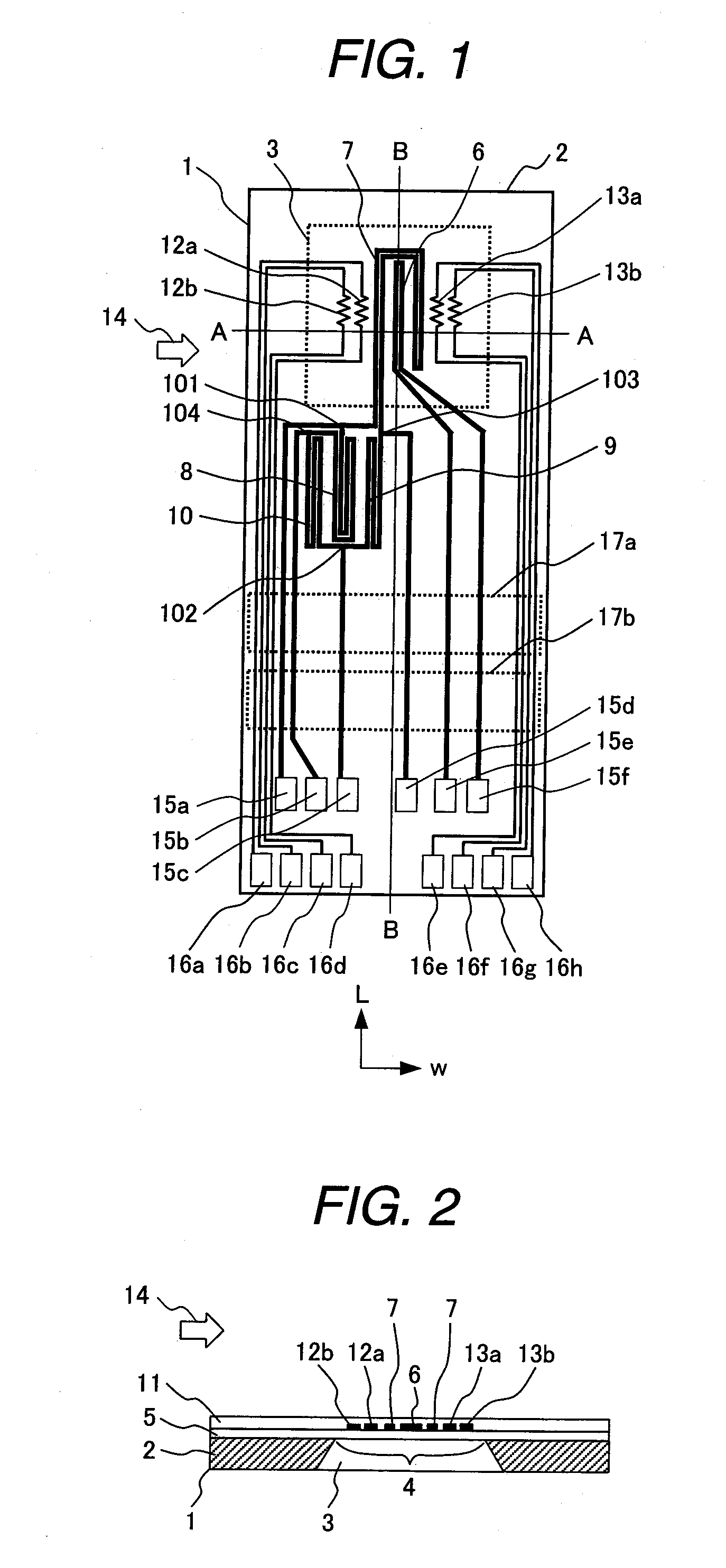
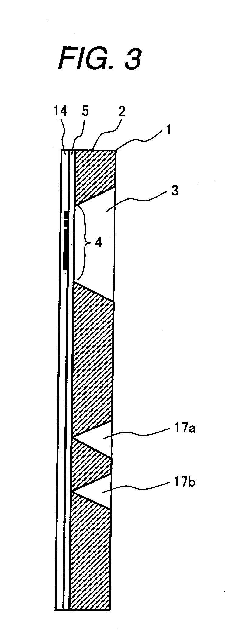
[0057]FIG. 1 is a schematic plan view showing a sensor element of a thermal type flow sensor according to this embodiment. FIG. 2 is a schematic diagram taken along a section A-A in FIG. 1, and FIG. 3 is a schematic diagram taken along a section B-B. In those figures, a base of a sensor element 1 is formed of a semiconductor substrate 2 such as a single crystal silicon (Si) plate. The semiconductor substrate 2 has a cavity portion 3 as a recess portion formed by subjecting one surface of the semiconductor substrate 2 to anisotropic etching. The planar configuration of the cavity portion 3 is square. One surface of the cavity portion 3 is formed with a diaphragm (thin-walled portion) 4. The diaphragm 4 is formed of an electric insulating film 5 that covers one surface of the semiconductor substrate 2. The electric insulating film 5 is made of silicon dioxide (S102) that is produced through thermal oxidation or a CVD (chemical vapor deposition) process.

[0058]Heat resistive elements 6,...

second embodiment

[0094]In the above embodiment, the temperature difference between the upstream and the downstream from the heat resistive elements (the temperature difference are formed by the heat resistive elements 6 and 7) is sensed by the temperature sensitive resistive elements 12a, 12b and 13a, 13b, to thereby sense the flow rate. Instead, it is possible to convert the current change that flows through the heat resistive element into an electric signal to sense the flow rate. For example, as shown in FIG. 26, the configuration of the sensor element can be proposed as follows. Namely, the sensor element is configured to sense the heating current for heat resistive elements at precedence position to the heat resistive elements 6 and 7 (the precedence position is located between the transistor 20 and the heat resistive elements 6, 7) and to convert the sensed current into a voltage to obtain an output 100. Thereby, the configuration makes it possible to sense the flow rate. Since the circuit sho...

third embodiment

[0095]FIG. 12 shows a plan view of a sensor element 26 according to this embodiment. A method of manufacturing the sensor element 26 is same as that of the first embodiment. The sensor element 26 is provided with a diaphragm (thin-walled portion) 27 as well as the first embodiment. Heat resistive elements 28, 29, 30, and temperature sensitive resistive elements 31a, 31b, 32a, and 32b are formed on the area of the diaphragm 27. Temperature sensitive resistive elements 33 and 34 are formed on places outside the diaphragm 27. As described above, the heat resistive element 29 corresponds to the first resistive element, the heat resistive element 30 corresponds to the fourth resistive element, and the heat resistive element 28 corresponds to the fifth resistive element.

[0096]FIG. 13 shows a driver circuit 35 of the sensor element 26. The bridge circuit is configured by connecting a first series circuit with a heat resistive element 29 (first resistive element) and a temperature sensitive...


PUM


Abstract

A thermal type flow sensor measures a flow rate of a fluid by means of a heat resistive element having a temperature dependency. The sensor is comprised of: plural heat resistive elements used for a flow rate measurement; and a driver circuit for controlling a current applied to these heat resistive elements to cause their heating. The driver circuit is configured to sense a resistance change of a lower-temperature side heat resistive element among the plural heat resistive elements and to control the current to be applied to the plural heat resistive elements in accordance with a sensed value of the lower-resistance's variation.

Description

CLAIM OF PRIORITY[0001]The present application claims priority from Japanese application serial no. 2006-027221, filed on Feb. 3, 2006, the contents of which are hereby incorporated by references into this application.BACKGROUND ART[0002]The present invention relates to a thermal type flow sensor that measures a flow rate of a fluid such as air flow by using a heat resistive element (temperature sensitive resistive element) having a temperature dependency.[0003]The thermal type flow sensor controls a current flowing through a heat resistive element so as to maintain a temperature difference between the heat resistive element whose heat is taken away with the fluid to be measured and a temperature compensation resistor a constant temperature difference. In order to carry out the current control, the thermal type flow sensor includes a bridge circuit with the heat resistive element and the temperature compensation resistive element and a driver circuit which controls the current flowi...

Claims


Application Information

Patent Timeline
Patent Type & Authority Applications(United States)
IPC IPC(8): G01F1/692
CPCG01F1/684G01F1/6845G01F1/692G01F1/698
Inventor NAKANO, HIROSHIYAMADA, MASAMICHIMATSUMOTO, MASAHIROWATANABE, IZUMI
Owner HITACHI ASTEMO LTD
Why Eureka
Try Eureka