Fast response photochromic composition and device

a composition and photochromic technology, applied in the direction of optical elements, vinyl aromatic copolymer adhesives, instruments, etc., can solve the problems of slow photochromic reaction time, heavy photochromic mineral glass lenses, and limited use of photochromic materials, so as to achieve fast back and forth fast change from transparent to tinted

Inactive Publication Date: 2013-09-19
KILOLAMBDA TECH
View PDF2 Cites 12 Cited by
  • Summary
  • Abstract
  • Description
  • Claims
  • Application Information

AI Technical Summary

Benefits of technology

[0021]The present invention further concerns, but is not limited to, the production of windows, lenses, contact lenses, microlenses, mirrors, filters and other optical articles, and the production of special optical elements against sun blinding, flash blinding, flash dazzling, flashing lights originating from explosions in the battle fields, welding light, fire related blinding, and lenses for cameras to look directly at th...

Problems solved by technology

The use of photochromic materials, however, has been very limited due to (a) degradation of the photochromic property of the materials from continued exposure, absorption and heating of ultra-violet (UV) light, particularly short wavelength (780 nm), and (b) the long rise and decay times of the darkening (up to minutes).
However, photochromic mineral glass lenses are heavy and have a slow photochromic reaction time, particularly in the change from dark to light.
However, for various reasons this objective has not been satisfactorily achieved with the existing plastic lenses.
However, this solution to the problem has limitations and drawbacks, such as the solution (a) is directed to forming a lens having...

Method used


Image

  • Fast response photochromic composition and device
  • Fast response photochromic composition and device
  • Fast response photochromic composition and device

Examples


examples

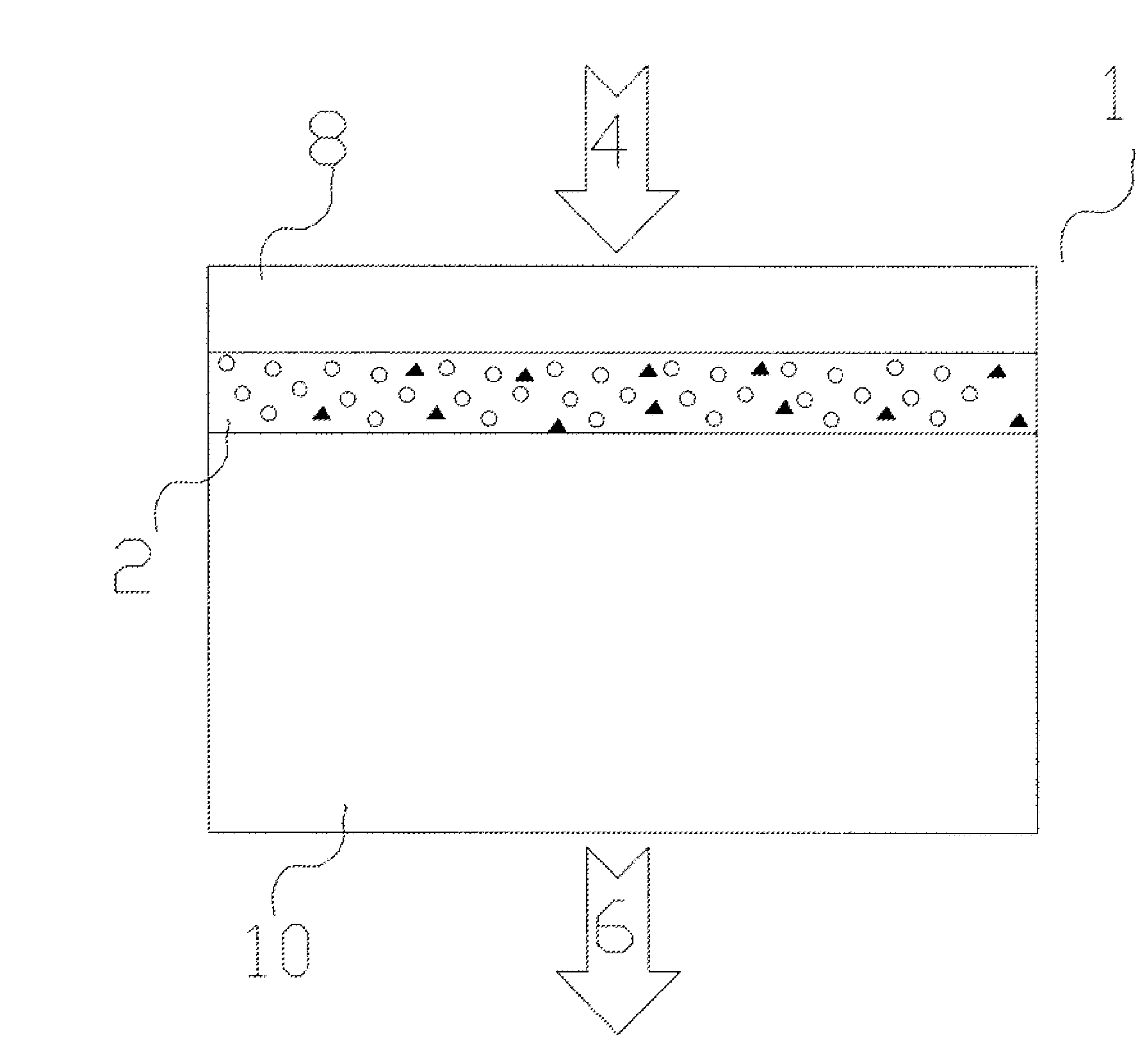
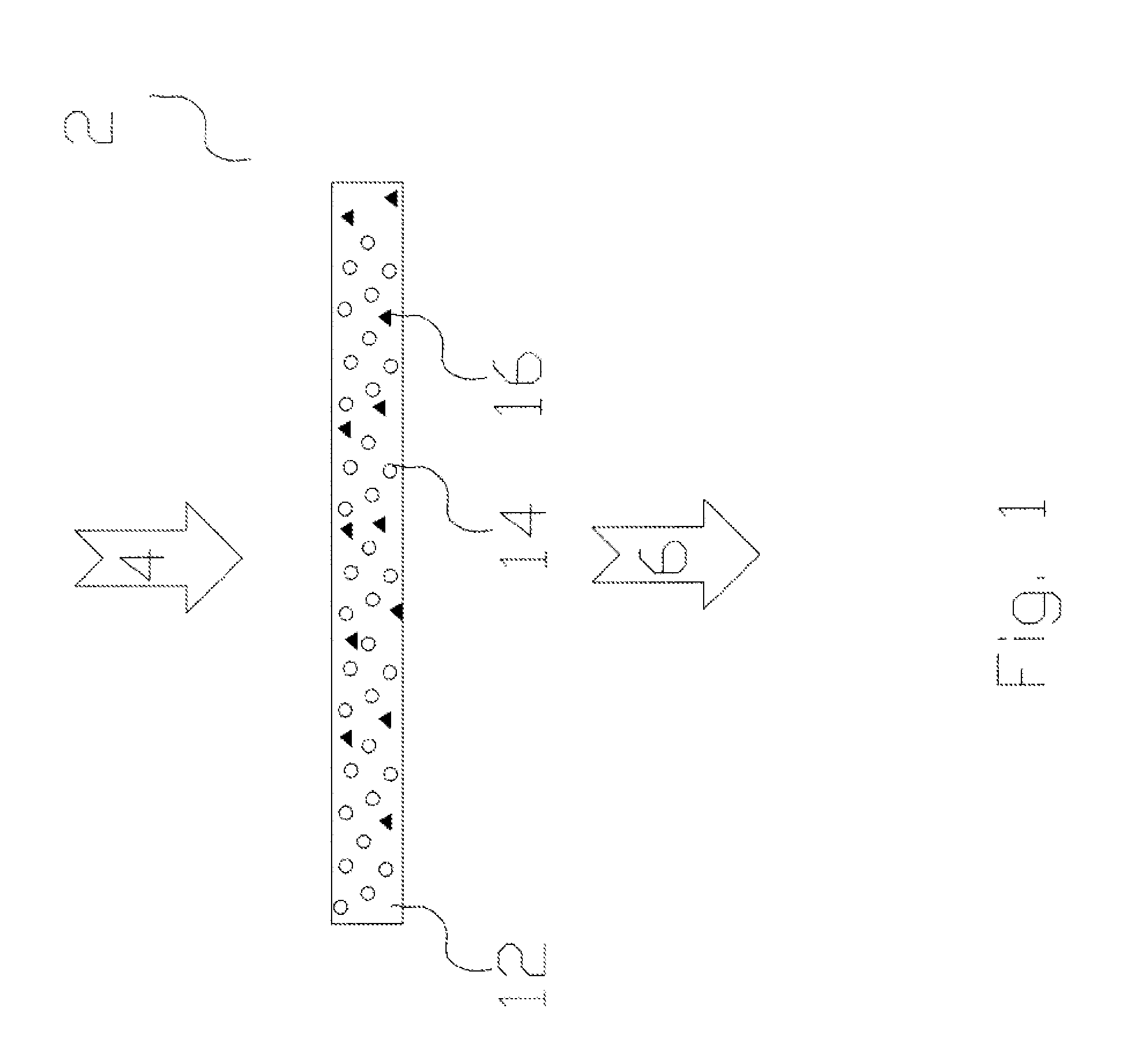
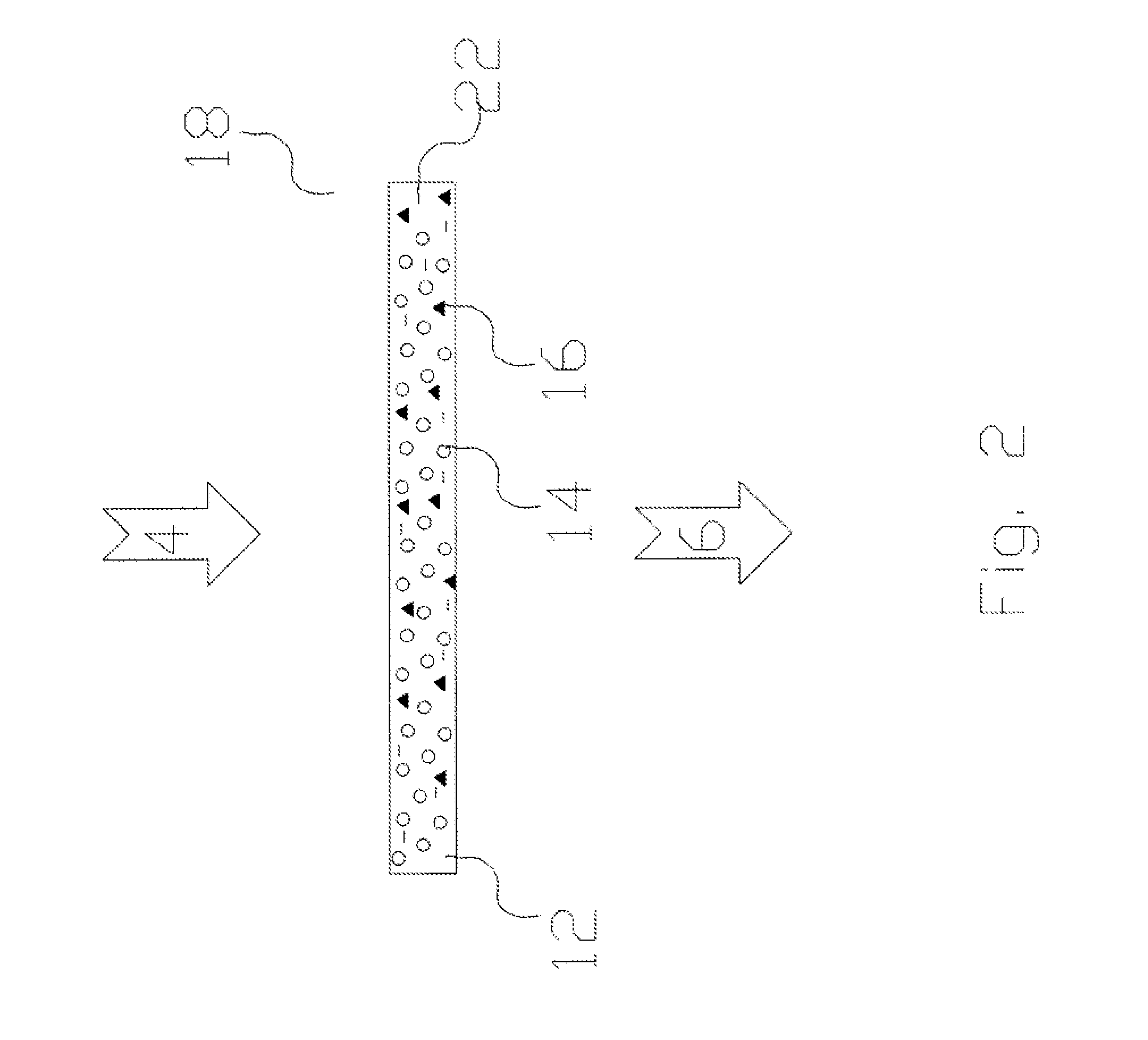
[0045]Example: This Example demonstrates a composition of materials for creating a fast responding photochromic laminate, prepared and tested at the applicants laboratory.

[0046]The preparation of the three component photochromic laminate is as follows: A 25 mL vial is filled with 2 gr of a polyurethane adhesive as a matrix, 0.04 gr of a photochromic dye (Vivimed Labs Europe) as the photochromic material and 0.02 gr of carbon nanotubes coated with silver nanoparticles (Bioneer Corporation) as the thermal conductivity enhancing additive. The mixture is sonicated using an ultrasonic finger (Vibra Cell VCX-130), to disperse the nanotubes, and is further magnetically stirred until all the photochromic dye dissolves. A laminate is formed by applying an approximately 100 micron thick layer between two glass slides. The laminate is then exposed to UV light to cure the adhesive. Alternatively, the laminate cured by placing the laminate in an oven at 80° C. for 60 hours.

[0047]Testing of the p...


PUM

PropertyMeasurementUnit
Fractionaaaaaaaaaa
Fractionaaaaaaaaaa
Fractionaaaaaaaaaa

Abstract

The present invention relates to optical power-limiting device, and more particularly, to an optical power-limiting passive device and to a method for limiting optical power transmission in lenses and windows, using absorption changes in a photochromic material with a fast response, featuring under a millisecond rise time and one to five seconds return/decay time.

Description

FIELD OF THE INVENTION[0001]The present invention relates to optical power-limiting device, and more particularly, to an optical power-limiting passive device and to a method for limiting optical power transmission in lenses and windows, using absorption changes in a photochromic material with a fast response, featuring under a millisecond rise time and one to five seconds return / decay time. Such ultra-fast response times were not realized in the past.[0002]The present invention further concerns, but is not limited to, the production of windows, lenses, contact lenses, microlenses, mirrors and other optical articles. Special optical elements against sun blinding, flash blinding, flash dazzling, flashing lights originating from explosions in the battle fields, welding light, fire related blinding, and lenses for cameras that look directly at the sun or missile launching, and other bright emitting sources.[0003]The present invention further concerns uses of the limiter for power regul...

Claims


Application Information

Patent Timeline
IPC IPC(8): G02B1/04G02B5/23
CPCC09J133/08C09J133/10G02B5/23G02B1/04C09J135/06C08K5/0041C08K7/00C09J9/00C09J11/06C09J175/04
Inventor OFIR, YUVALDONVAL, ARIELAORON, MOSHEVEVO, DORON
Owner KILOLAMBDA TECH
Why Eureka
Try Eureka