
Signal wire

Inactive Publication Date: 2010-07-08
CHANG ROSA
View PDF4 Cites 3 Cited by
  • Summary
  • Abstract
  • Description
  • Claims
  • Application Information

AI Technical Summary

Benefits of technology

[0010]Another objective of this invention is to provide a signal wire capable of enduring repeated bending with low impedance to enhance the transmission efficiency thereof.
[0024]Thereby, as compared to the conventional technology, the signal wire can have a significantly decreased external diameter while still having relatively low impedance to make it suitable for use in minute instruments. The flexibility of the signal wire can improve the bending tolerance of the signal wire so that no break or fracture will occur to the signal wire even when it is repeatedly bent in use. Moreover, this invention may further simplify the production procedure, speed up the production process and lower the production cost.

Problems solved by technology

Common conventional solid signal wires used in environments where repeated bending is expected, such as electronic product connections, stereo equipment, loudspeakers, vibrating instruments and audio cables, often are fatigued or fractured due to frequent vibration or bending.
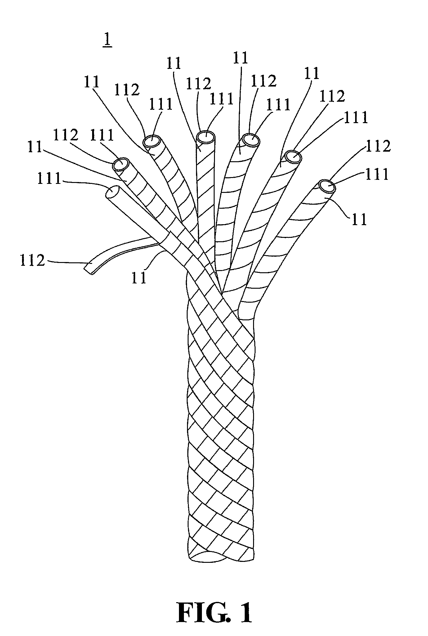
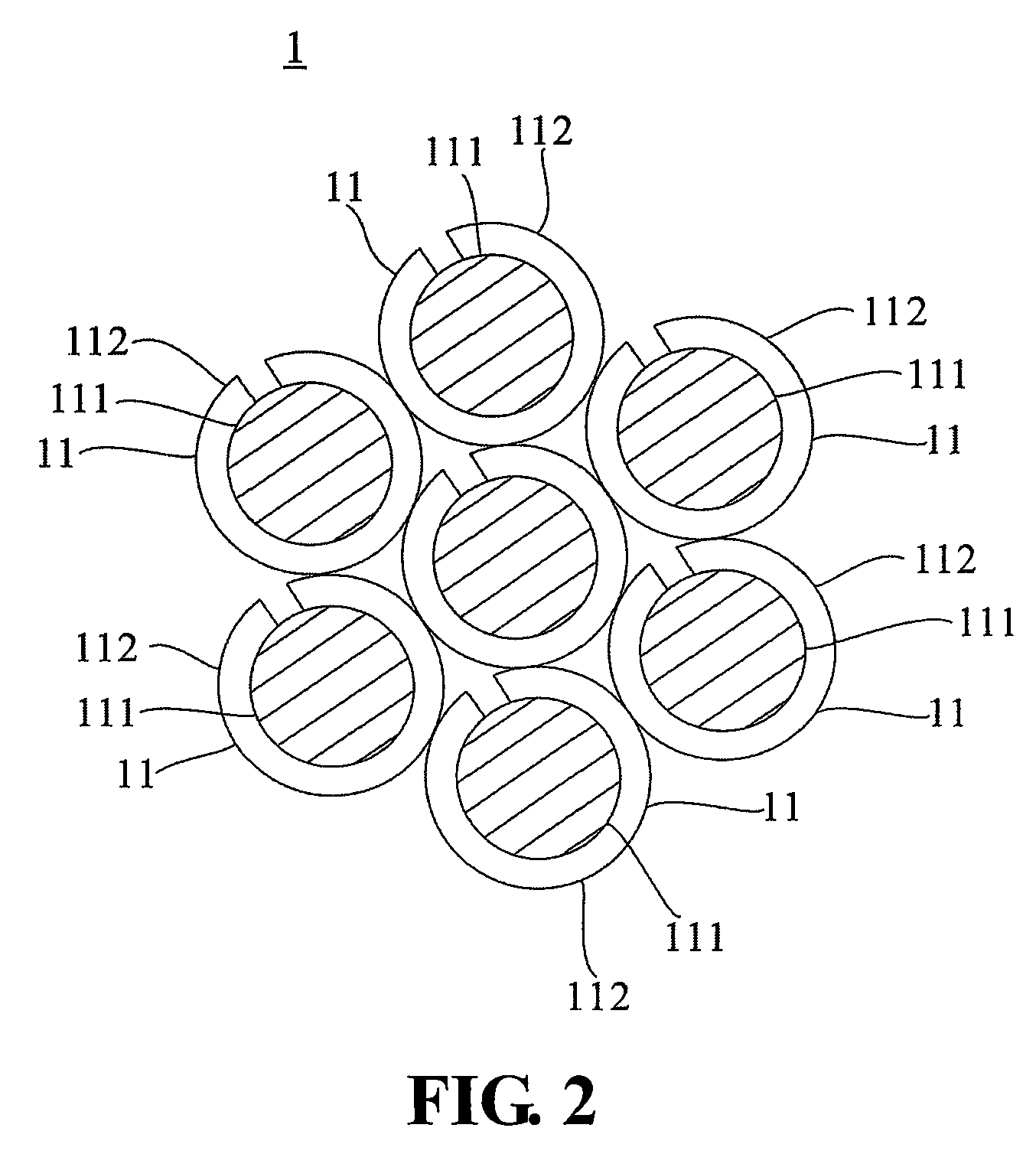
However, when signals are transmitted among the metal foil wires 11, it is usually difficult for the signals to overcome the surface resistance that arises when the wound metal foil straps 112 come into contact with each other to propagate along a longitudinal direction of each metal foil wire 11 directly.
However, increasing the number of metal foil wires 11 leads to a thicker external diameter of the convention signal wire 1, making it unsuitable for use in minute instruments such as hearing aids.

Method used


Image

  • Signal wire
  • Signal wire
  • Signal wire

Examples


Embodiment Construction

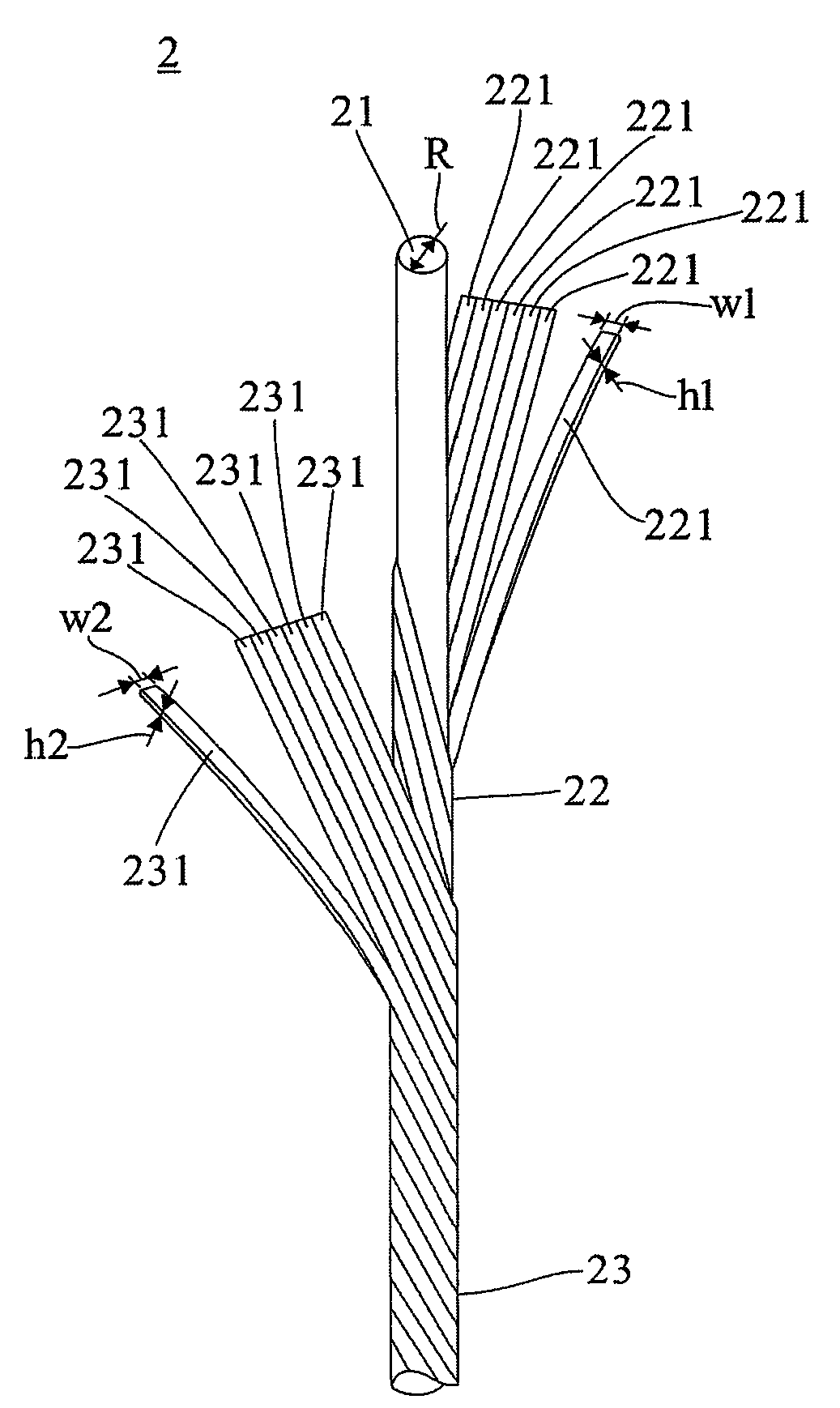
[0030]A signal wire 2 according to an embodiment of this invention is depicted in FIGS. 3 and 4. FIG. 4 is drawn on an exaggerated scale to show the profile of individual metal foil straps 221 and 231 more clearly; and it shall be appreciated that in practical use, the metal foil straps 221 and 231 may not have a gap therebetween and may even overlap with each other. The signal wire 2 of this embodiment at least comprises a flexible core 21 and a first metal layer 22. The flexible core 21 has a surface and a longitudinal direction, while the first metal layer 22 comprises a plurality of metal foil straps 221. The metal foil straps 221 of the first metal layer 22 are directly and helically wound in parallel, but not overlapped with each other, on the surface of the core 21 to form a continuously, electrically conductive structure along the longitudinal direction. The signal wire 2 of this invention comprises only a single core 21 which has an external diameter R approximately equal t...


PUM


Abstract

A signal wire which at least comprises a flexible core and a metal layer is disclosed. The flexible core has a surface and a longitudinal direction, and the metal layer comprises a plurality of metal foil straps. The metal foil straps are directly and helically wound in parallel on the surface of the core to form a continuously, electrically conductive structure along the longitudinal direction. Thereby, the signal wire has both a decreased external diameter and decreased impedance.

Description

[0001]This application claims priority to China Patent Application No. 200920001601.9 filed on Jan. 5, 2009.CROSS-REFERENCES TO RELATED APPLICATIONS[0002]Not applicable.BACKGROUND OF THE INVENTION[0003]1. Field of the Invention[0004]The present invention relates to a signal wire, and more particularly, to a signal wire capable of enduring repeated bending.[0005]2. Descriptions of the Related Art[0006]Various technical products, such as electronic product connections, stereo equipment, loudspeakers, earphone audio cables, and even precise medical appliances (e.g., hearing aids), must all transmit signals via signal wires. Because the transmission efficiency of the signal wires has an influence on the definition of the signals and the thickness in terms of the external diameter thereof also has an influence on the products' minuteness, the quality of the signal wires should be improved. Common conventional solid signal wires used in environments where repeated bending is expected, suc...

Claims


Application Information

Patent Timeline
IPC IPC(8): H01B5/08
CPCH01B5/102H01B7/0018
Inventor CHANG, ROSA
Owner CHANG ROSA
Learn More