Microanalytical chip
a microanalytical chip and microchip technology, applied in the field of microanalytical chips, can solve the problems of difficult to downsize the device as a whole, difficult to achieve the effect of stably controlling, simple and highly accurate manner
- Summary
- Abstract
- Description
- Claims
- Application Information
AI Technical Summary
Benefits of technology
Problems solved by technology
Method used
Image
Examples
embodiment 1
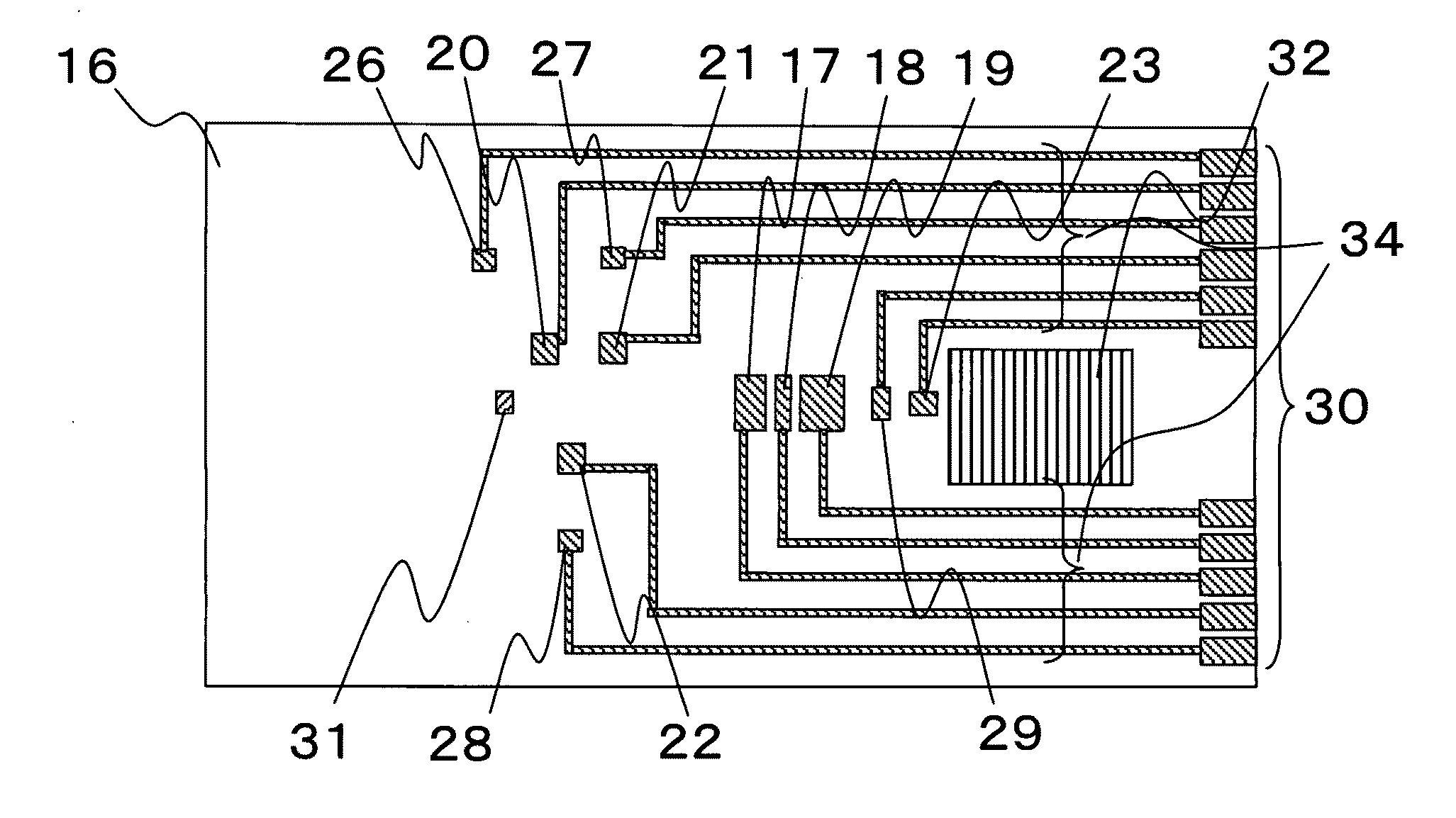
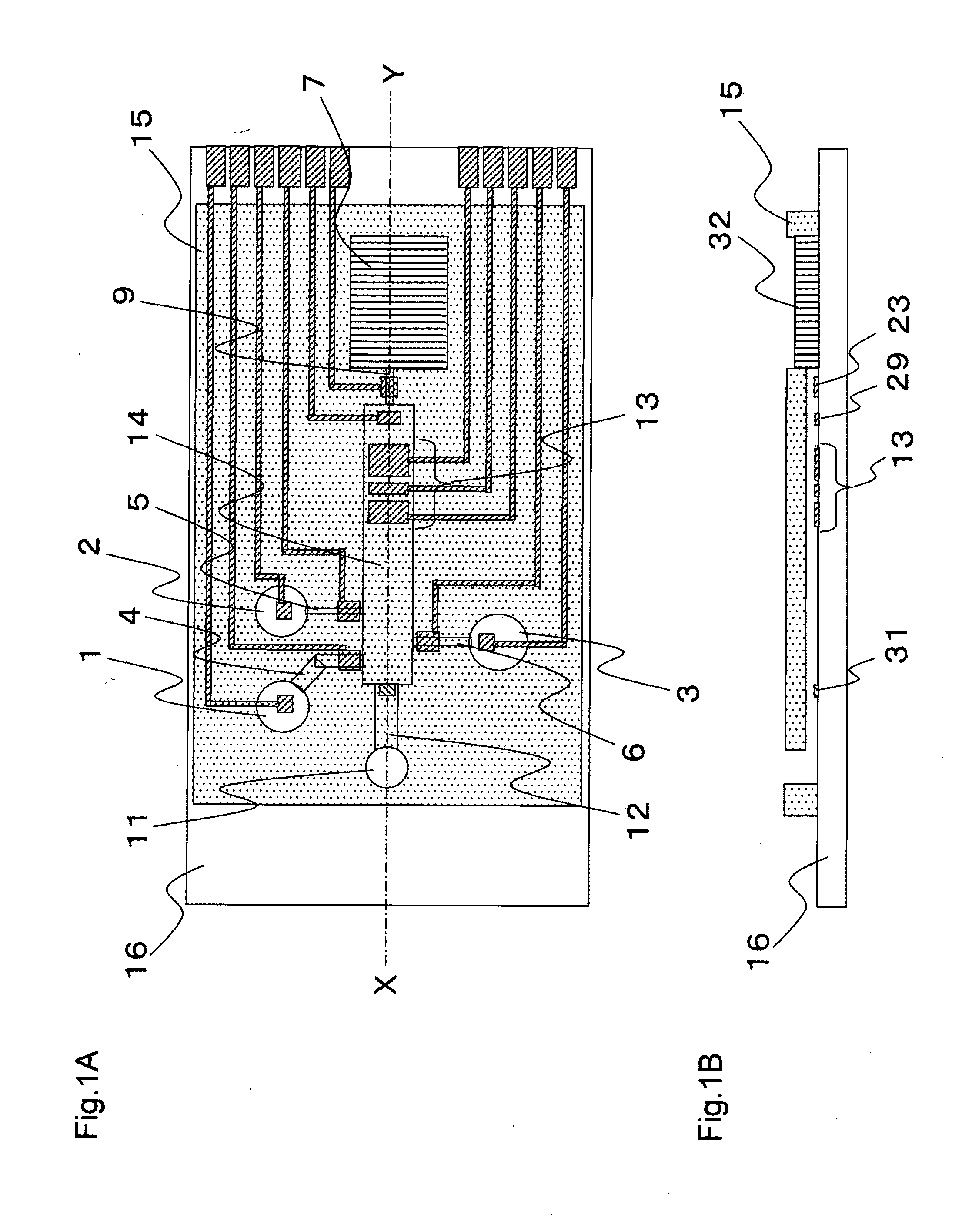
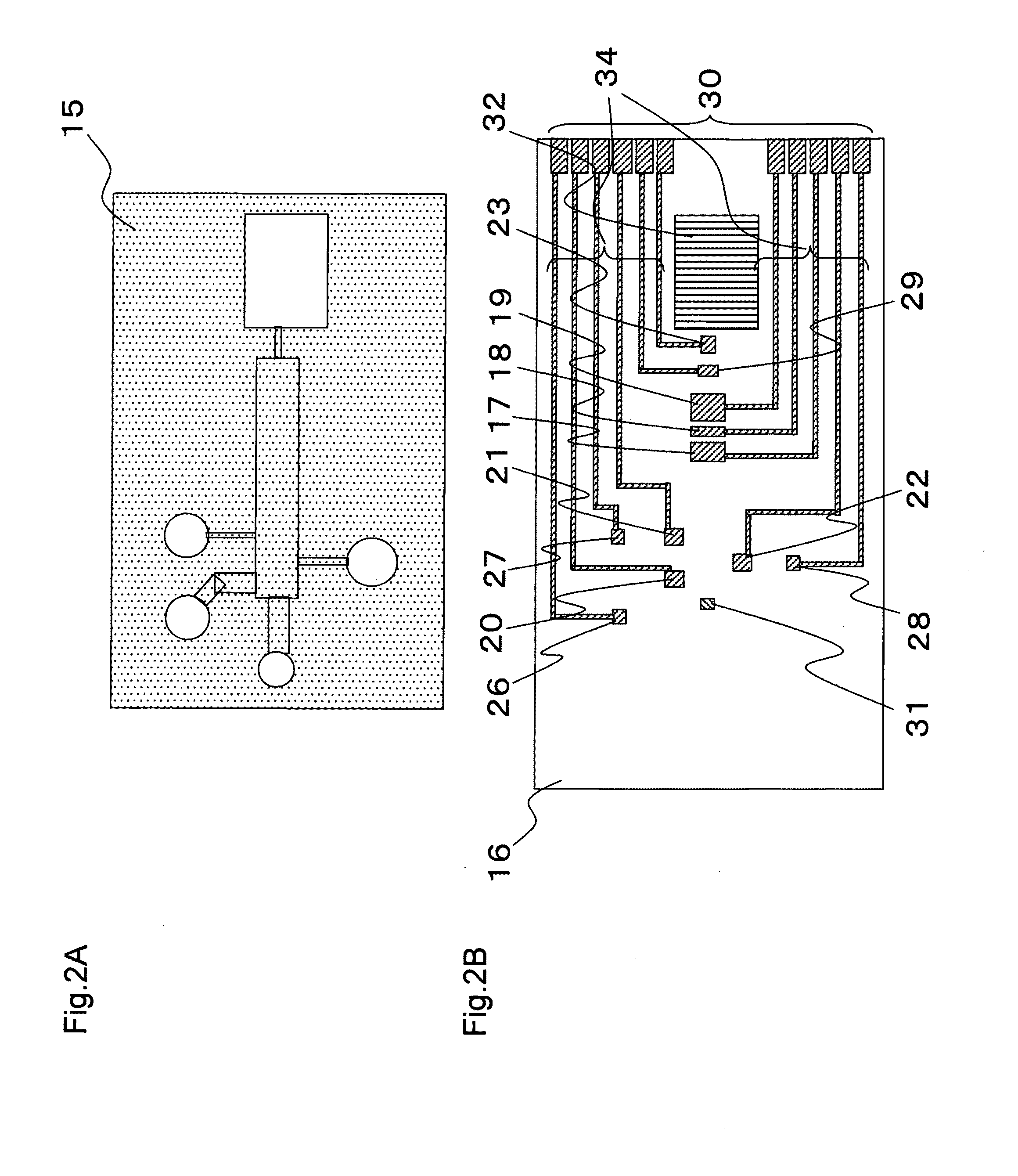
[0062]Referring to FIG. 1A, a microanalytical chip according to the present embodiment includes a main conduit 14 having a detecting portion 13, and open holes 1, 2, and 3 for introducing a solution into the chip. Also provided are first to third introduction conduits 4, 5, and 6 for introducing a solution to the main conduit 14 from a further upstream position than the detecting portion 13; a discharge conduit 9 provided on a downstream side of the main conduit; a discharge portion 7 provided on the discharge conduit 9 at its end; and an air flow path 12 connected to an air hole 11. The first to third introduction conduits 4, 5, and 6 are respectively provided with first to third valves for opening / closing solution flow.
[0063]FIG. 1B shows a X-Y cross section of FIG. 1A. The microanalytical chip according to the present embodiment is implemented by attaching a first substrate 15 having formed thereon grooves for the conduits and a second substrate 16 serving as a lid for the first ...
embodiment 2
[0114]Description will be made of a microanalytical chip of a structure different from embodiment 1 by referring to the drawings.
[0115]FIG. 7 shows a microanalytical chip according to the present embodiment.
[0116]The microanalytical chip according to the present embodiment is similar to embodiment 1 except that the introduction conduit 4 has a preliminary treatment portion 50 for carrying out preliminary treatment of liquid (such as separation of solid content and decomposition of a multimer). Thus, only the preliminary treatment portion 50 will be described in detail, with description of already-described portions omitted.
[0117]FIG. 8A is a plan view of the preliminary treatment portion 50 and FIG. 8B is a side view thereof. The first substrate 15 and the second substrate 16 are formed in the same manner as in embodiment 1.
[0118]The preliminary treatment portion 50 has a separation treatment portion 51 for removing erythrocyte contained in the blood sample serving as a measurement ...
example 1
[0128]The present example relates to embodiment 1.
[0129]FIGS. 3, 4A, and 4B show a microanalytical chip according to the present example.
[0130]Referring to FIG. 3, the microanalytical chip according to the present example includes first to third introduction conduits 4, 5, and 6 respectively having open holes 1, 2, and 3 for introducing liquid to inside the chip, discharge conduits 9 and 10 respectively connected to two discharge portions 7 and 8, and an air flow path 12 connected to an air hole 11, all of which are connected to a main conduit 14 having a detecting portion 13.
[0131]Referring to FIGS. 4A and 4B, the microanalytical chip is composed of two substrates. A first substrate 15 has formed thereon a groove for the main conduit 14, thorough holes for the open holes 1, 2, and 3, grooves for the first to third introduction conduits 4, 5, and 6, grooves for the discharge conduits 9 and 10, holes for the discharge portions 7 and 8, a groove for the air flow path 12, and a thoroug...
PUM
| Property | Measurement | Unit |
|---|---|---|
| Temperature | aaaaa | aaaaa |
| Thickness | aaaaa | aaaaa |
| Electric potential / voltage | aaaaa | aaaaa |
Abstract
Description
Claims
Application Information
 - R&D
- Intellectual Property
- Life Sciences
- Materials
- Tech Scout
- Unparalleled Data Quality
- Higher Quality Content
- 60% Fewer Hallucinations
Browse by: Latest US Patents, China's latest patents, Technical Efficacy Thesaurus, Application Domain, Technology Topic, Popular Technical Reports.
© 2025 PatSnap. All rights reserved.Legal|Privacy policy|Modern Slavery Act Transparency Statement|Sitemap|About US| Contact US: help@patsnap.com


