LED package methods and systems

a technology of led package and packaging, applied in transportation and packaging, semiconductor devices for light sources, light and heating apparatuses, etc., can solve problems such as inefficiency, lack of reliability and longevity, and introduction of side effects, and achieve the effect of reducing utility problems

Active Publication Date: 2010-07-08
SIGNIFY NORTH AMERICA CORP
View PDF101 Cites 143 Cited by
  • Summary
  • Abstract
  • Description
  • Claims
  • Application Information

AI Technical Summary

Benefits of technology

[0043]Provided herein are methods and systems for providing a power factor-corrected line v

Problems solved by technology

Power supplies used in LED lighting systems have often been based on power supplies for conventional lighting systems or other electronic devices, leading to problems of inefficiency, lack of reliability and lack of longevity.
Over the years, the increased acceptance and use of fluorescent and HID lamps has increased the use of electronics to drive loads and these devices, along with computers and appliances, have introduced some side effects due to the ballasts and power supplies they incorporate.
The electrical current these newer systems draw is very different from resistive loads and introduces issues for electricity

Method used


Image

  • LED package methods and systems
  • LED package methods and systems
  • LED package methods and systems

Examples


Embodiment Construction

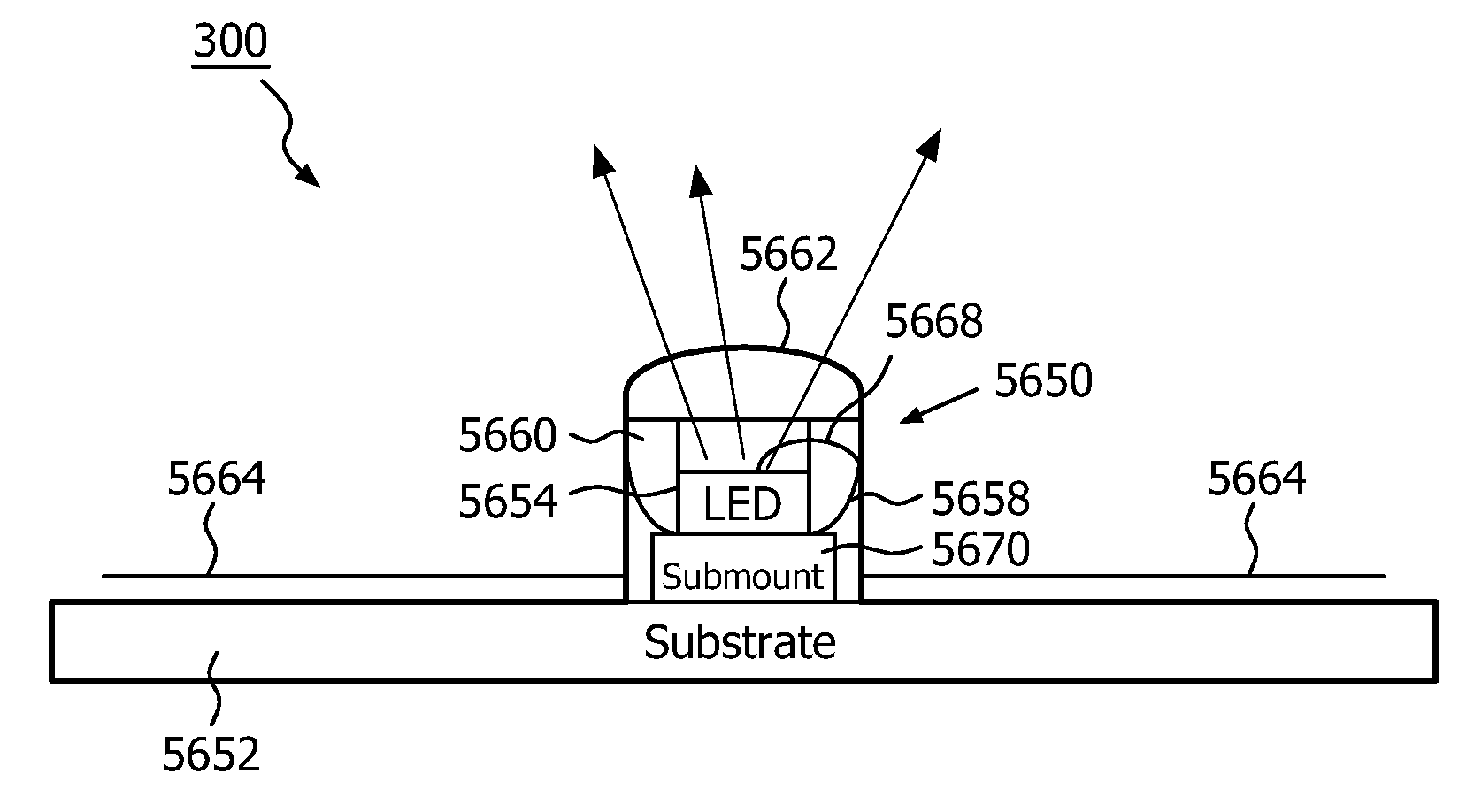
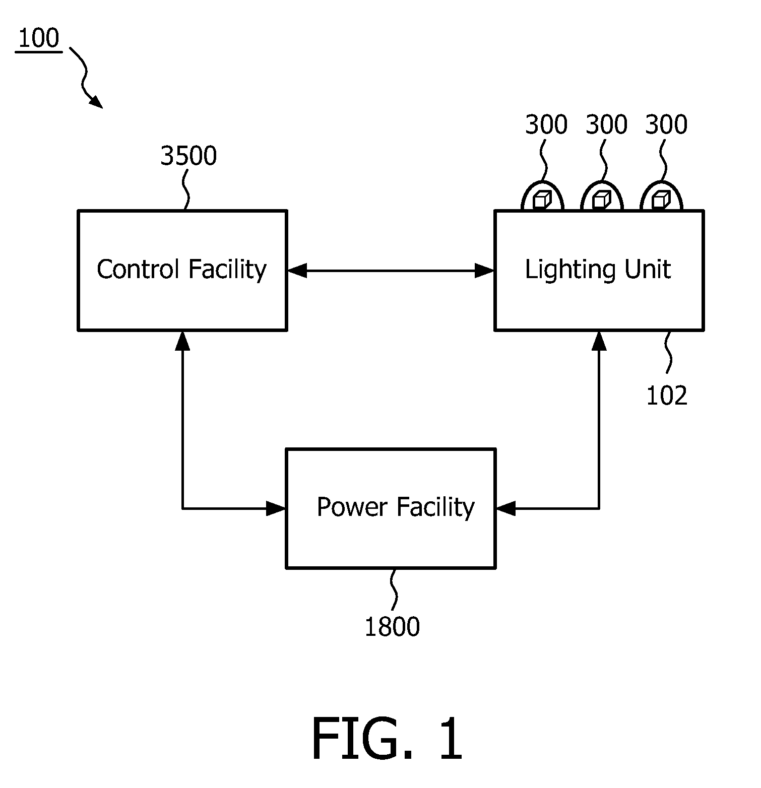
[0176]Referring to FIG. 1, in a lighting system 100 a lighting unit 102 is controlled by a control facility 3500. In embodiments, the control facility 3500 controls the intensity, color, saturation, color temperature, on-off state, brightness, or other feature of light that is produced by the lighting unit 102. The lighting unit 102 can draw power from a power facility 1800. The lighting unit 102 can include a light source 300, which in embodiments is a solid-state light source, such as a semiconductor-based light source, such as light emitting diode, or LED.

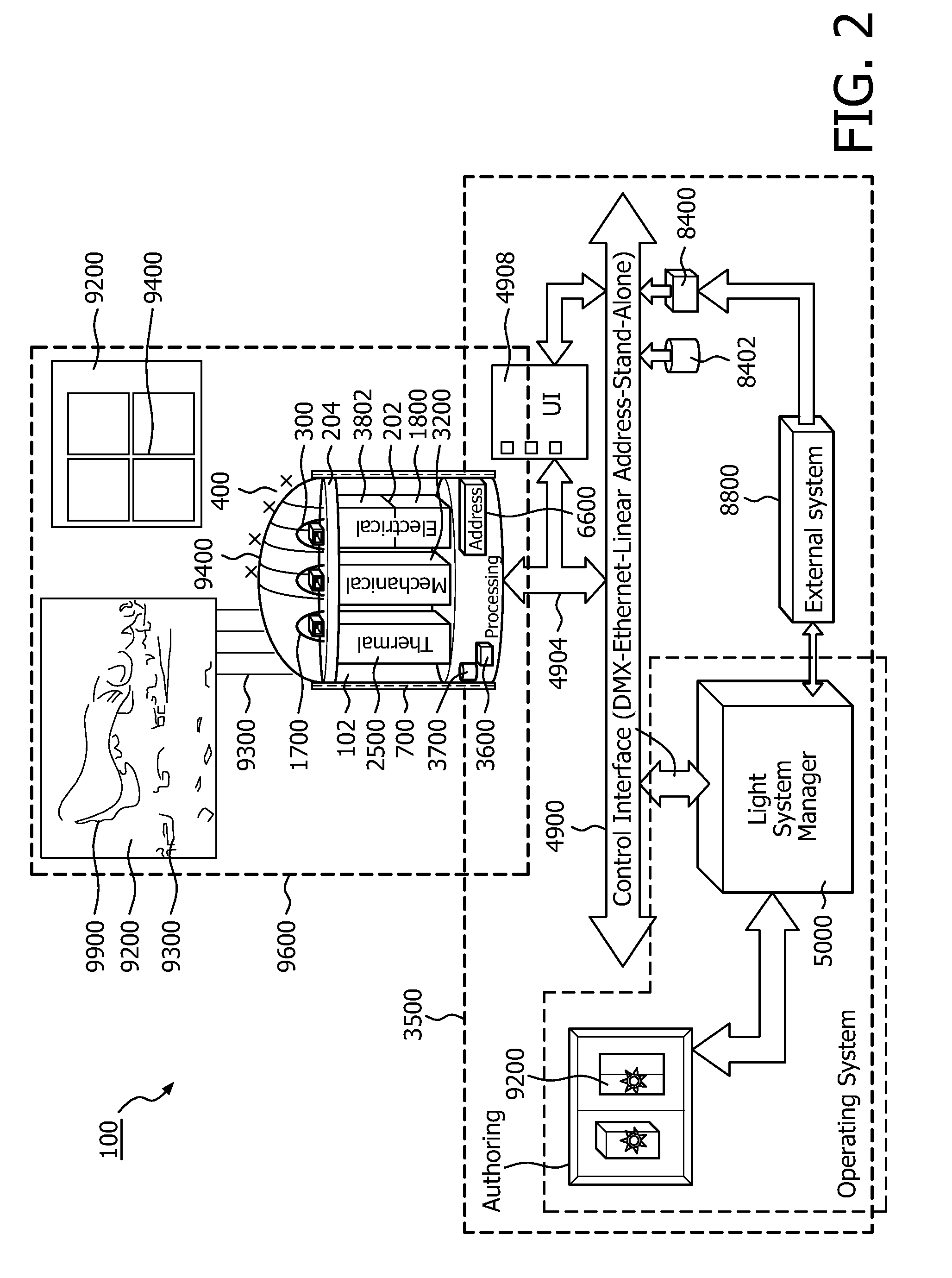
[0177]Referring to FIG. 2, the system 100 can be a solid-state lighting system and can include the lighting unit 102 as well as a wide variety of optional control facilities 3500.

[0178]In embodiments, the system 100 may include an electrical facility 202 for powering and controlling electrical input to the light sources 300, which may include drive hardware 3802, such as circuits and similar elements, and the power facility 1800...


PUM


Abstract

Methods and systems are provided for LED modules that include an LED die integrated in an LED package with a submount that includes an electronic component for controlling the light emitted by the LED die. The electronic component integrated in the s submount may include drive hardware, a network interface, memory, a processor, a switch-mode power supply, a power facility, or another type of electronic component.

Description

CROSS-REFERENCE TO RELATED APPLICATIONS [0001]The present application claims the benefit, under 35 U.S.C. §119(e), of the following U.S. provisional applications:[0002]Ser. No. 60 / 586,939, filed Jul. 8, 2004, entitled “Integrated LED Systems and Methods;” and[0003]Ser. No. 60 / 588,090, filed Jul. 15, 2004, entitled “LED Package Methods and Systems.”[0004]Each of the foregoing applications is incorporated herein by reference.BACKGROUND [0005]LED packages have been developed that include an LED die and a submount that includes a diode, such as an ESD diode. However, current LED packages require manufacturers to develop and implement many separate electronic components in order to power the LED dies and to control the light coming from the LED dies. A need exists to simplify the challenges of powering and controlling LED packages.[0006]Power supplies used in LED lighting systems have often been based on power supplies for conventional lighting systems or other electronic devices, leadin...

Claims


Application Information

Patent Timeline
IPC IPC(8): H01L33/48F21K99/00
CPCF21K9/00F21S45/47H05B33/0803H05B33/0815H05B33/0818H05B33/0821H05B33/0842H05B33/0863H05B33/0869H05B33/0872H05B33/089Y02B20/346H01L25/167F21S45/46F21S45/43F21S45/42H05K1/0306H05K2201/10106H01L2224/73265H01L2924/1461H01L2224/48091H01L2924/00014H01L2924/00H05B45/20H05B45/40H05B45/22H05B45/50H05B45/56H05B45/375H05B45/3725H05B45/38H05B45/325H05B45/355H05B45/385H01L2224/2612Y02B20/30
Inventor MORGAN, FREDERICK M.LYS, IHOR A.DOWLING, KEVIN J.MUELLER, GEORGE G.
Owner SIGNIFY NORTH AMERICA CORP
Why Eureka
Try Eureka