Integrated composite electromechanical machines

Inactive Publication Date: 2010-07-08
YOSHYAMA EMIKO MRS
View PDF11 Cites 9 Cited by
  • Summary
  • Abstract
  • Description
  • Claims
  • Application Information

AI Technical Summary

Benefits of technology

[0018]In an embodiment, configuring or changing the functionality of a rotor/stator pair includes making the rotor/stator pair become either a nonoperation part, a motor or a generator. For example, changing the functionality of a rotor/stator pair can include changing a motor configuration to a generator configuration, and vice versa. The controller can change the function of the composite electromechanical machine to accommodate different situations. For example, a composite electromechanical machine can comprise two rotor/stator pairs. For high motor power, the controller can configure the two rotor/stator pairs to be motor, combining their power. For reducing power, the controller can configure one rotor/stator pair to be nonoperation, such as no power or a small power to offset the magnetic braking is supplied to the rotor, the stator, or rotor/stator pair, leaving one rotor/stator pair to carry the load. If th

Problems solved by technology

However, this classification is not a rigid distinction, especially with advan

Method used


Image

  • Integrated composite electromechanical machines
  • Integrated composite electromechanical machines
  • Integrated composite electromechanical machines

Examples


Embodiment Construction

[0031]Embodiments of the invention include an integrated composite motor or generator which comprises multiple rotor / stator pairs that are configured as a double-sided stator and / or double-sided rotor. The integrated composite electromechanical machine can comprise a plurality of concentric machines or a combination of concentric machines with planar machines.

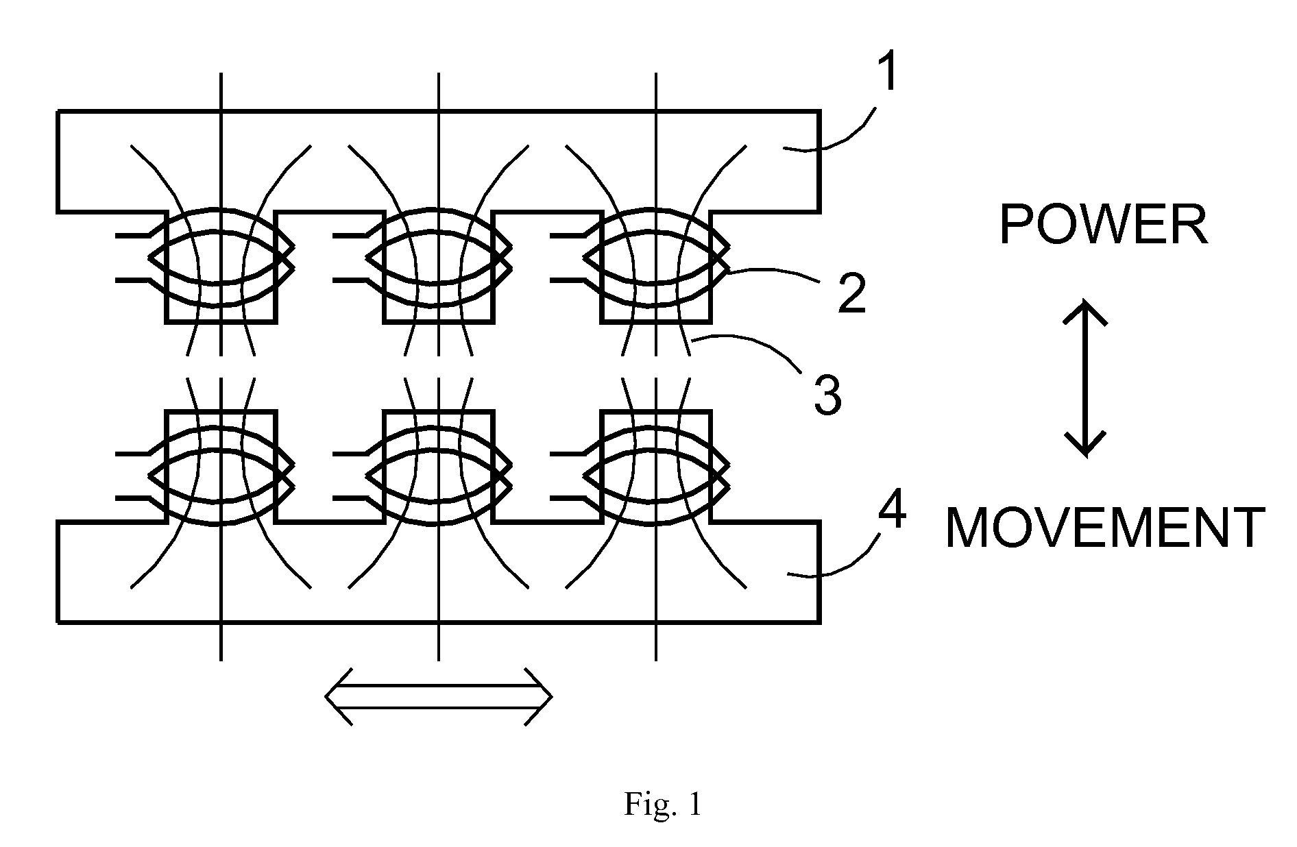
[0032]FIG. 1 illustrates the interaction of magnetic field(s) in a motor or generator. A power can be applied to a magnetic plane 1, for example, through the windings 2, to generate a magnetic field 3. Interaction of the magnetic field 3 with another magnetic plane 4 can provide a movement for this magnetic plane 4. Conversely, movement of the magnetic plane 4 can generate power within the windings 2 of the magnetic plane 1. In this configuration, certain magnetic field is directed away from the interaction, and thus does not contribute to the power transfer

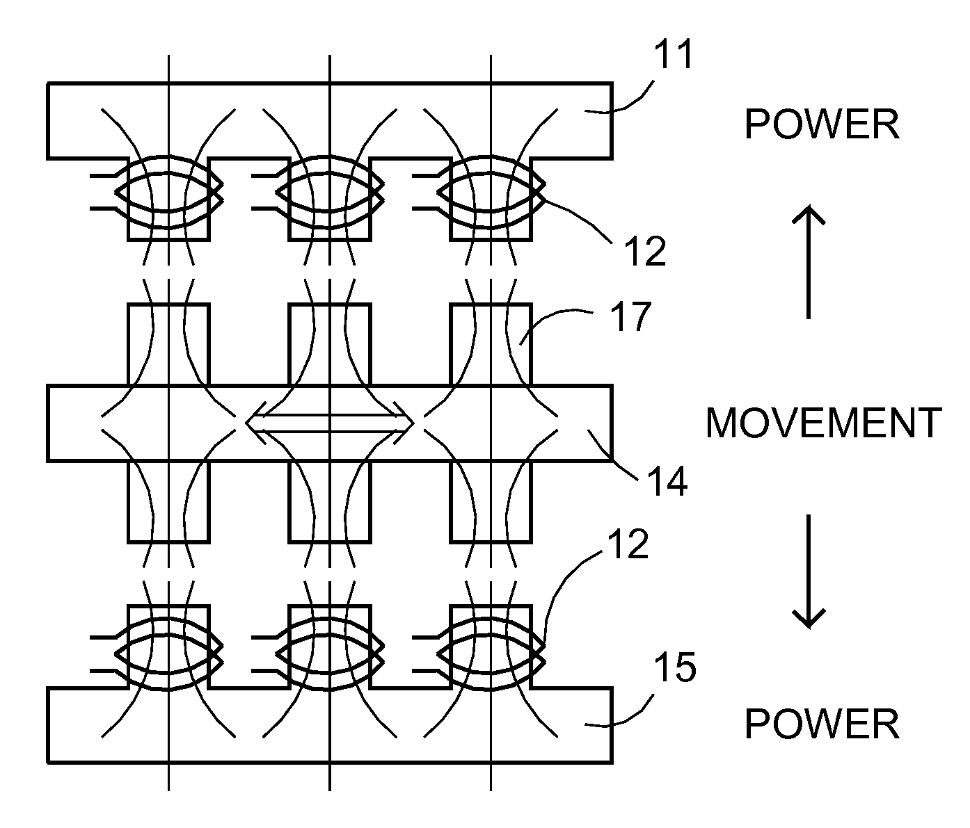
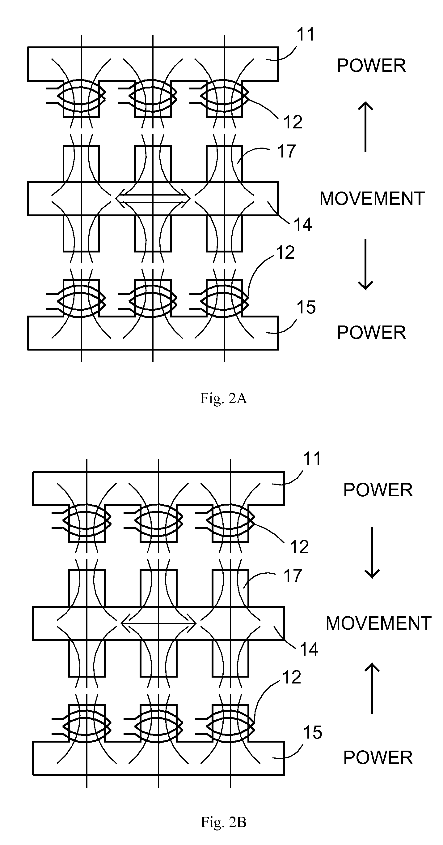
[0033]FIG. 2A illustrates a schematic for a generator using a double-si...


PUM


Abstract

Embodiments of the present invention include a composite electromechanical machine which can operate as a motor or a generator (including dynamo or alternator). In an aspect, the present composite electromechanical machine comprises at least double-sided magnetic planes (e.g., rotor or stator) disposed on both sides of a central frames. Other embodiments can also be included.

Description

[0001]The present invention is related to application Ser. No. 12 / 210,169, filing date Sep. 12, 2008, entitled “Composite electromechanical machines with gear mechanism”, and to application Ser. No. 12 / 210,171, filing date Sep. 12, 2008, entitled “Composite electromechanical machines with uniform magnets”, hereby incorporated by reference.[0002]The present invention relates generally to electromechanical machines, such as motor, generator, dynamo, or alternators, and particularly to composite electromechanical machines.BACKGROUND[0003]Electromechanical machines such as alternator(s), motor(s), dynamo(s), and generator(s) can convert energy between mechanical energy and electrical energy. For example, an electric motor uses electrical energy to produce mechanical energy, and a generator or dynamo uses mechanical energy to produce electrical energy. In general, an electromechanical machine can operate as a motor or as a generator, depending on the applied input energy. The major diffe...

Claims


Application Information

Patent Timeline
IPC IPC(8): H02P6/00H02K21/12
CPCH02K16/00H02K21/12
Inventor QUERE, ERIC STEPHANE
Owner YOSHYAMA EMIKO MRS
Why Eureka
Try Eureka