Charge System, Mobile Electronic Device, Cell Terminal Used for Them, and Secondary Cell

a mobile electronic device and charge system technology, applied in the direction of secondary cell servicing/maintenance, cell components, cell component details, etc., can solve the problem that normal charge control cannot be performed, and achieve the effect of preventing an increase in the consumption of electric power and restricting the size of secondary batteries

Inactive Publication Date: 2010-07-08
KYOCERA CORP
View PDF10 Cites 26 Cited by
  • Summary
  • Abstract
  • Description
  • Claims
  • Application Information

AI Technical Summary

Benefits of technology

[0017]The present invention can provide: a charge system that can verify whether a proper secondary battery is installed, while not only preventing an increase in the consumption of electric power as much as possible, but also restraining the sizes of the secondary battery and a mobile electronic device; the mobile electronic device; a battery terminal used for the mobile electronic device; and the secondary battery.

Problems solved by technology

If a battery that is not a regular one, and which is an imitation or accidentally has the same terminal arrangement as the regular battery is installed in a mobile electronic device, it may be that normal charge control can not be performed.

Method used


Image

  • Charge System, Mobile Electronic Device, Cell Terminal Used for Them, and Secondary Cell
  • Charge System, Mobile Electronic Device, Cell Terminal Used for Them, and Secondary Cell
  • Charge System, Mobile Electronic Device, Cell Terminal Used for Them, and Secondary Cell

Examples


Embodiment Construction

[0032]A detailed description is given of an embodiment of a mobile electronic device and a secondary battery according to the present invention with reference to the drawings.

[0033]FIGS. 1-12 are drawings that are referenced so as to describe a cellar phone 2 (an example of the mobile electronic device), a battery terminal 60 provided inside the cellar phone 2 and a secondary battery 30 installed in the cellar phone 2.

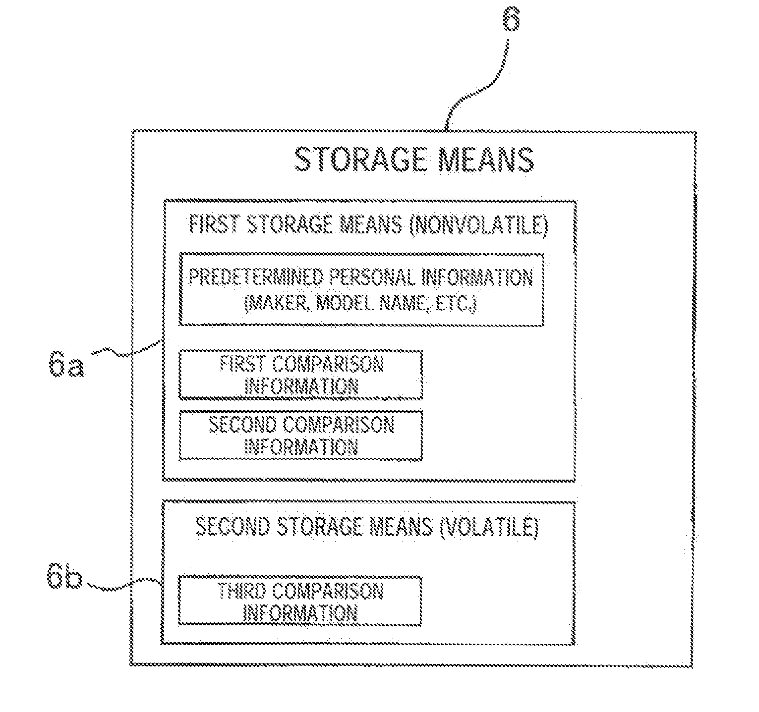
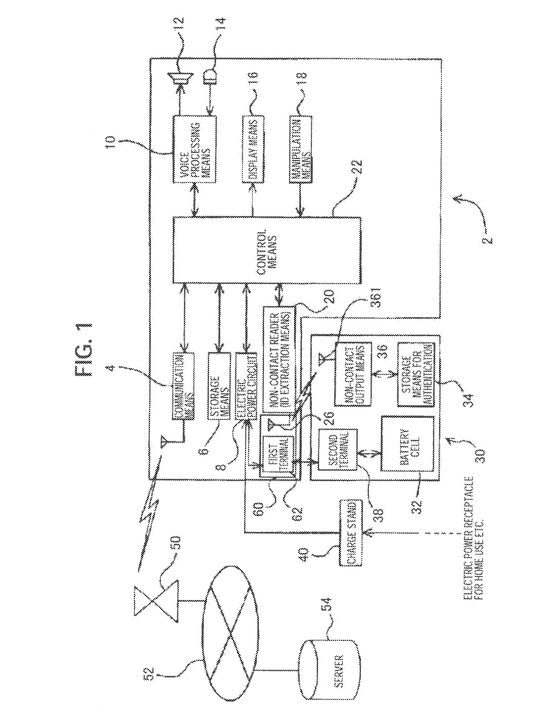
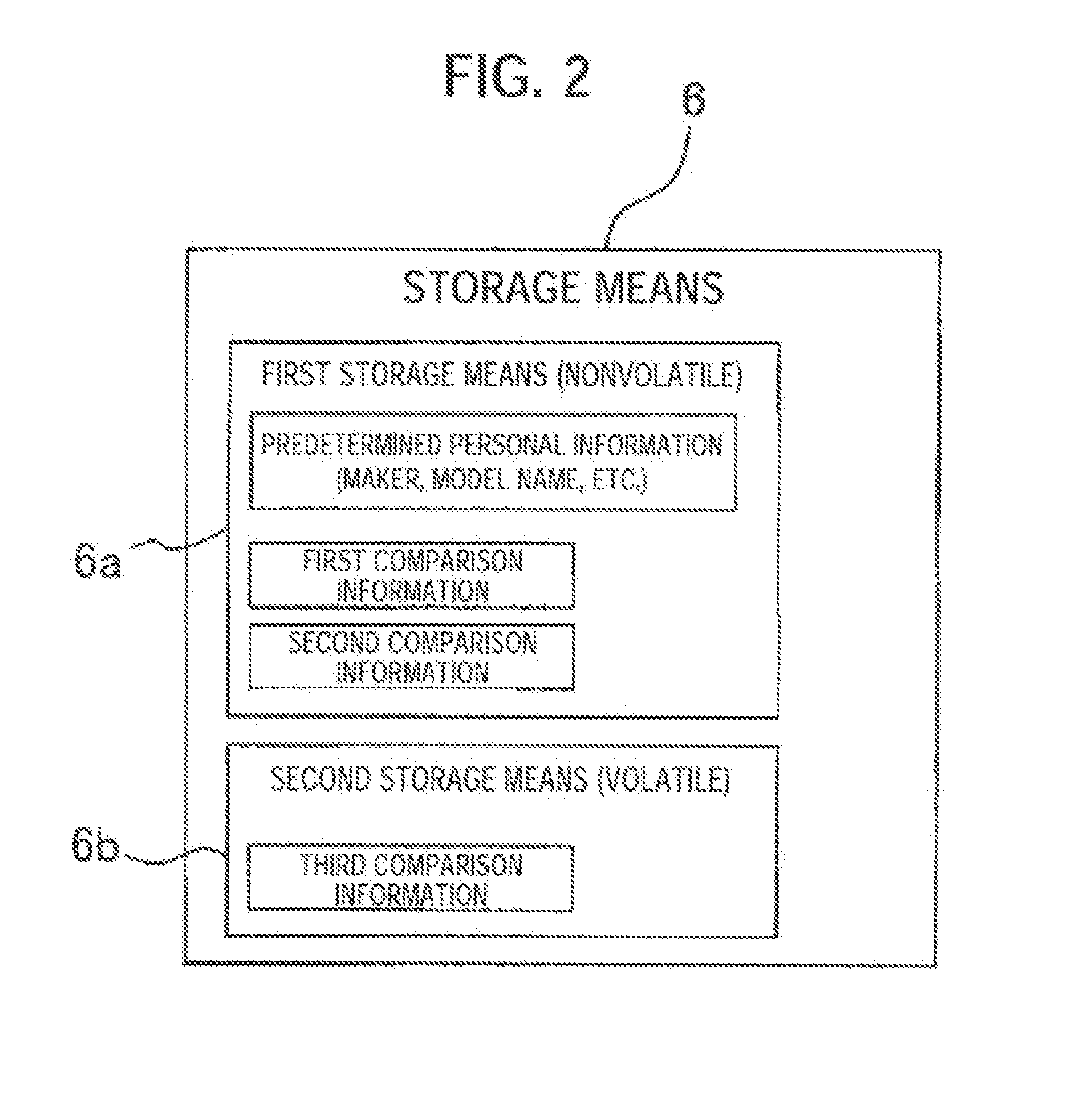
[0034]FIG. 1 is a block diagram illustrating a circuit architecture for the cellar phone 2 installed with the secondary battery 30. The cellar phone 2 includes communication means 4, storage means 6, electric power circuit 8, voice processing means 10, speaker 12, microphone 14, display means 16, manipulation means 18, battery terminal 60, non-contact reader 20 (corresponding to an ID extraction means) and control means 22 that controls these components. The battery terminal 60 is provided with an RFID antenna 26 that is connected with a first terminal 62 and the non-c...


PUM

PropertyMeasurementUnit
chargeaaaaaaaaaa
electric poweraaaaaaaaaa
magnetic fieldaaaaaaaaaa

Abstract

It is possible to prevent charge of an incompatible secondary cell while suppressing the size of a mobile electronic device and a secondary cell without increasing power consumption so as to prevent damage of the secondary cell or the mobile electronic device by charge. A detachable secondary cell (30) supplies power to a mobile electronic device (2). The mobile electronic device (2) includes: a cell terminal (60) which outputs and inputs power to / from the mounted secondary cell (30); non-contact information extraction means (20) which performs a magnetic field communication; a loop antenna (26) which transmits / receives a signal using an electromagnetic wave by the non-contact information extraction means (20); and control means (22) which acquires particular information outputted from the non-contact information extraction means (20) and controls charge of the secondary cell (30) according to the acquired particular information. The loop antenna (26) is arranged in the cell terminal (60).

Description

TECHNICAL FIELD[0001]This invention relates to a charge system that is connectable to a charging device and in which a secondary battery is attachably and detachably installed and when a mobile electronic device is connected with the charging device while the second battery is installed therein, electric power is automatically supplied from the charging device to the secondary battery, and mobile electronic device, and a battery terminal used for the mobile electronic device, and the secondary battery.BACKGROUND ART[0002]For a conventional mobile electronic device such as a cellar phone, a secondary battery is adapted to be attachably and detachably installed, which is connectable to a predetermined charging device and compatible with the mobile electronic device. There has been a device belonging to such a mobile electronic device, which includes an electric power circuit that automatically starts electric power supply from a charging device to a secondary battery, when the mobile ...

Claims


Application Information

Patent Timeline
Patent Type & Authority Applications(United States)
IPC IPC(8): H02J7/00H01M50/574H01M50/588H01Q1/24H01Q7/00H01Q7/06H02J7/02H04M1/02H04M1/72412H04M1/73
CPCH01M2/1066H01M2/34H01M10/425H01M10/46H02J7/0009H04M1/0214H04M1/0262H04M1/7253H02J7/00043H02J7/00047Y02E60/10H04M1/72412H01M50/588H01M50/574
Inventor NAKAJIMA, MASAYOSHIKOYAMA, AKIRA
Owner KYOCERA CORP
Why Eureka
Try Eureka