
Draw Tape Bag

a technology of draw tape and tape, which is applied in the field of draw tape bags, can solve the problems of increasing the force of draw tape, affecting the performance of draw tape, and unable to meet the requirements of withstanding satisfactorily the force applied to draw tape, so as to improve the compatibility with heat sealing and improve the strength

Inactive Publication Date: 2010-07-08
THE GLAD PROD CO
View PDF9 Cites 30 Cited by
  • Summary
  • Abstract
  • Description
  • Claims
  • Application Information

AI Technical Summary

Benefits of technology

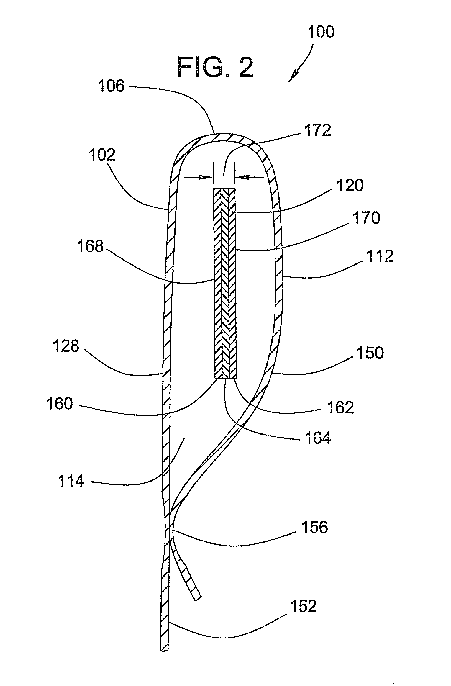
[0003]The draw tape bag may include a machine direction oriented draw tape with improved strength and improved compatibility with heat sealing. In one embodiment, the draw tape bag may comprise a bag body defining a cavity and a rim, the rim defining a mouth to the bag. The bag may comprise a hem including a passageway, the hem defining at least one opening. The bag may further comprise at least one multilayer polyolefin draw tape disposed within the hem. The draw tape may include a first skin layer, a second skin layer, and at least one core layer disposed between the skin layers. The draw tape is machine direction oriented. The core layer may be disposed between the skin layers and the skin layers may be exposed on the surface of the draw tape. The core layer may be comprised of high density polyethylene (HDPE) or medium density polyethylene (MDPE). The HDPE or MDPE of the core layer may be blended with other materials. The skin layers may be comprised of linear low density polyethylene (LLDPE) or low density polyethylene (LDPE). The LLDPE or LDPE of the skin layers may be blended with other materials.

Problems solved by technology

Because the draw tape represents the preferred feature by which a user will grip and manipulate a bag, the draw tape is subject to increased forces.
Prior draw tapes have not possessed the strength necessary to withstand satisfactorily the forces applied to the draw tapes.
Furthermore, many draw tapes typically wrinkle under forces associated with a user lifting a bag.
The wrinkling and / or yielding of the draw tape concentrates the weight of the bag on the user's hand thereby making it uncomfortable.

Method used


Image

  • Draw Tape Bag
  • Draw Tape Bag
  • Draw Tape Bag

Examples


Embodiment Construction

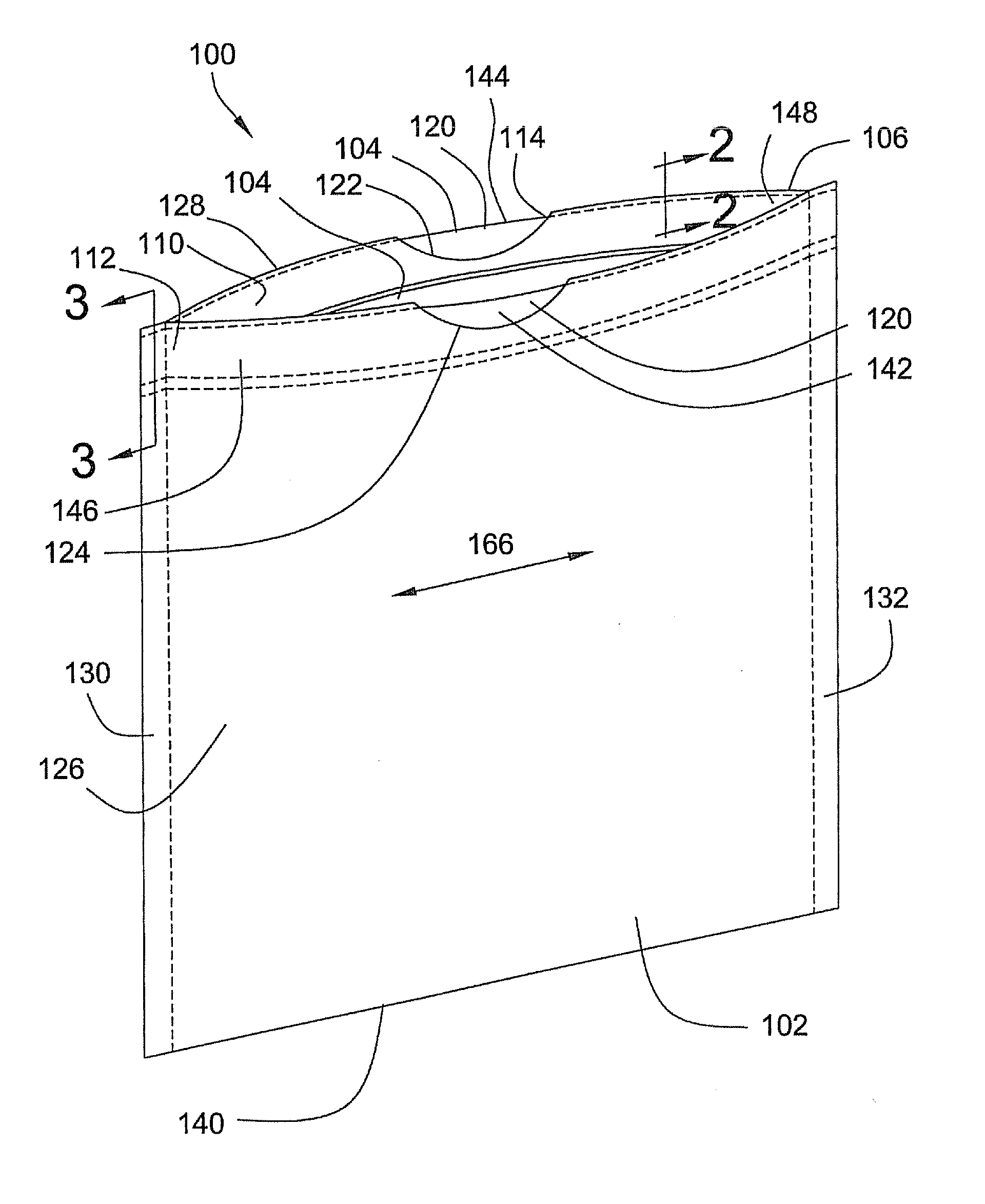
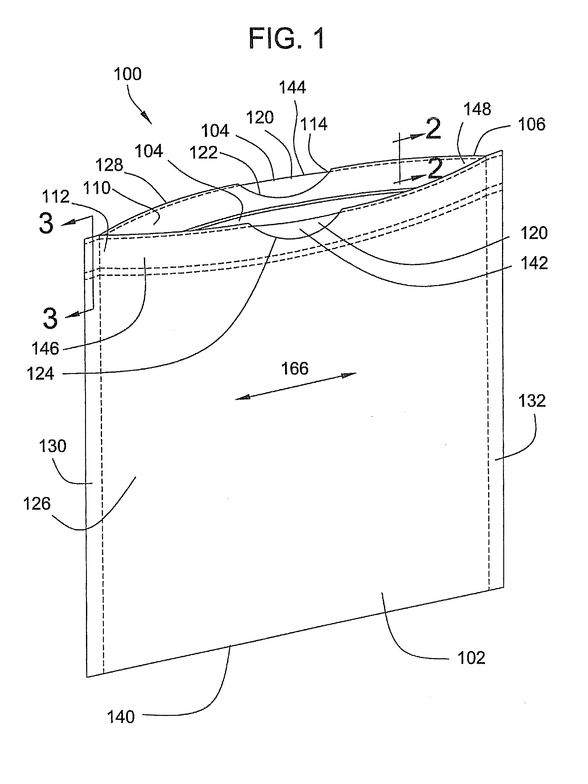
[0013]Referring to FIG. 1, a draw tape bag 100 may comprise a bag body 102 defining a cavity 104 and a rim 106, the rim 106 defining a mouth 110 to the bag 100. The bag 100 may include a hem 112 including a passageway 114. The bag 100 may further include at least one multilayer polyolefin draw tape 120 disposed within the passageway 114 of the hem 112. The draw tape 120 is a made from a multilayer film that has been subjected to machine direction orientation (MDO). The hem 112 may include a first opening 122 and a second opening 124 such that the draw tape 120 is accessible to a user at both openings 122, 124. The hem 112 may define the rim 106 so that the draw tape 120 is disposed at the rim 106 of the bag 100.

[0014]In one embodiment, the bag body 102 may comprise a front panel 126 and a back panel 128, wherein the front panel 126 and the back panel 128 are joined along a left side seam 130 and a right side seam 132, as shown in FIG. 1. The seams 130, 132 may extend from the rim 10...


PUM

PropertyMeasurementUnit
Thicknessaaaaaaaaaa
Thicknessaaaaaaaaaa
Densityaaaaaaaaaa

Abstract

The draw tape bag may include, a bag body defining a cavity and a rim, the rim defining a mouth to the bag. The bag may include a hem including a passageway, the hem defining at least one opening. The bag may further include at least one multilayer polyolefin draw tape disposed within the hem. The draw tape may include a first skin layer, a second skin layer, and at least one core layer disposed between the skin layers. The draw tape is machine direction oriented. The core layer may be located between the skin layers. The core layer may include high density polyethylene or medium density polyethylene. The skin layers may include low density polyethylene or linear low density polyethylene.

Description

BACKGROUND[0001]Draw tape bags including polyolefin draw tapes have been used for many years. The draw tapes provide a bag user a means to grip and manipulate a bag as well as providing a means for securing the bag closed. Because the draw tape represents the preferred feature by which a user will grip and manipulate a bag, the draw tape is subject to increased forces.[0002]Prior draw tapes have not possessed the strength necessary to withstand satisfactorily the forces applied to the draw tapes. The known draw tapes often yielded under the stresses applied by a user. Furthermore, many draw tapes typically wrinkle under forces associated with a user lifting a bag. The wrinkling and / or yielding of the draw tape concentrates the weight of the bag on the user's hand thereby making it uncomfortable.BRIEF SUMMARY[0003]The draw tape bag may include a machine direction oriented draw tape with improved strength and improved compatibility with heat sealing. In one embodiment, the draw tape b...

Claims


Application Information

Patent Timeline
IPC IPC(8): B65D33/28B29C47/06
CPCB65D33/28B32B27/32B32B7/12B32B27/08B32B27/306B32B27/308B32B27/327B32B2270/00B32B2307/31B32B2307/514B32B2307/54B32B2439/00
Inventor O'DONNELL, HUGH J.KENT, GREGORY S.STEPP, RENZY L.
Owner THE GLAD PROD CO
Learn More