Automatic pallet exchange device

Active Publication Date: 2010-07-08
PANASONIC CORP
View PDF5 Cites 3 Cited by
  • Summary
  • Abstract
  • Description
  • Claims
  • Application Information

AI Technical Summary

Benefits of technology

[0007]It is an object of the present invention to provide an automatic pallet exc

Problems solved by technology

However, when the pallet is exchanged only by linear movement of the arm, since the moving speed of the arm is the moving speed of the pallet, it is limited to shorten an exchanging time due to the restriction of a linearly moving mechanism.
Further, a

Method used


Image

  • Automatic pallet exchange device
  • Automatic pallet exchange device
  • Automatic pallet exchange device

Examples


Example

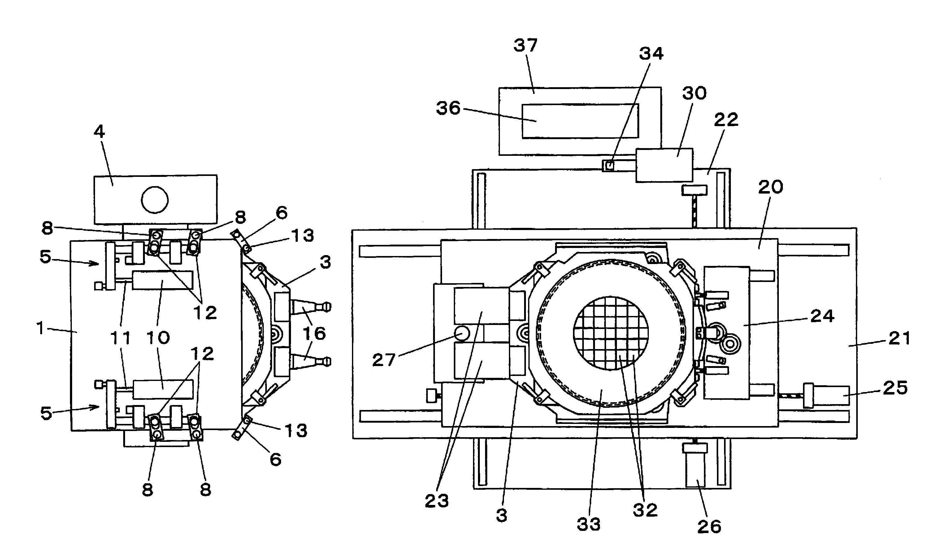
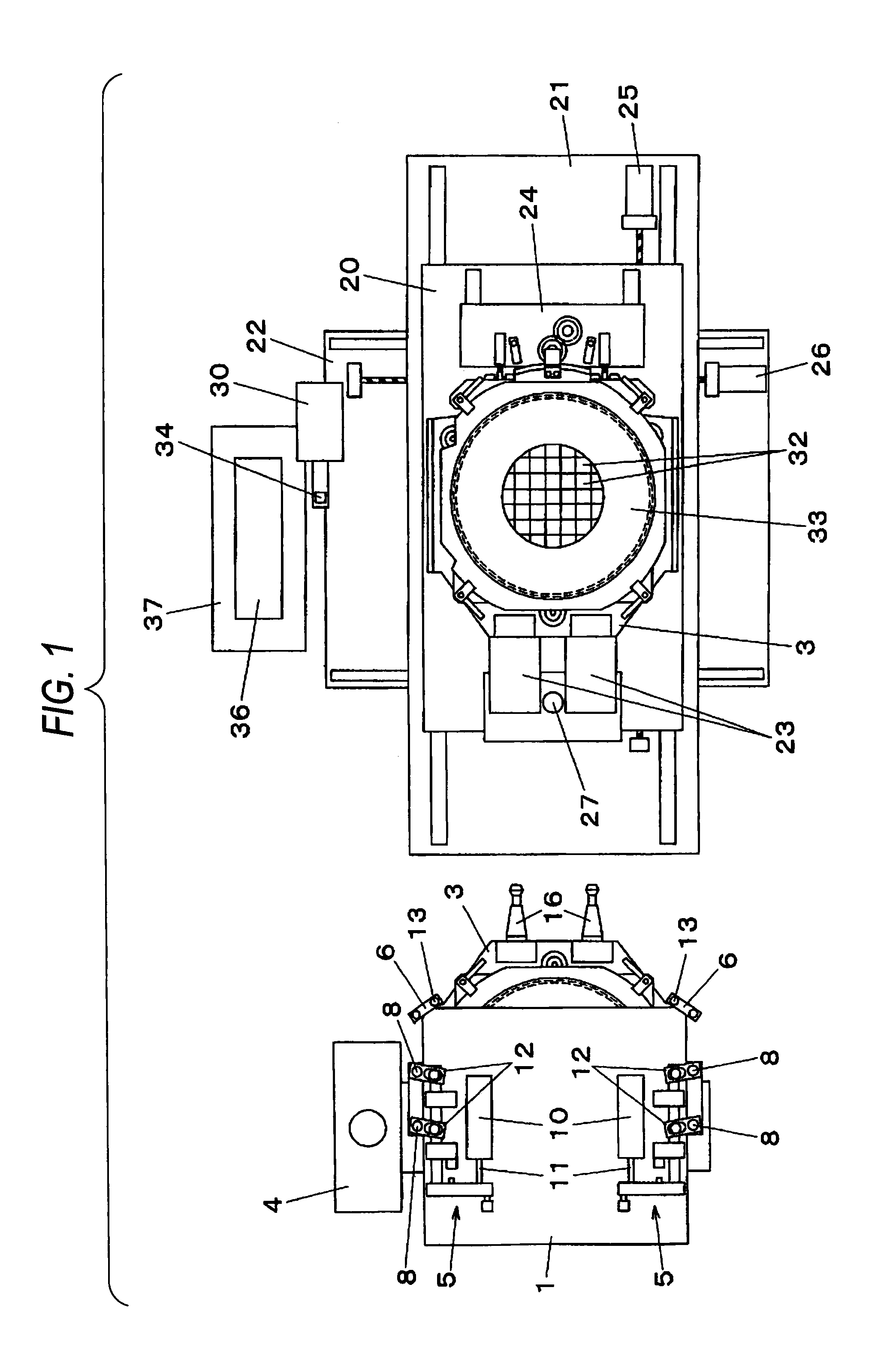
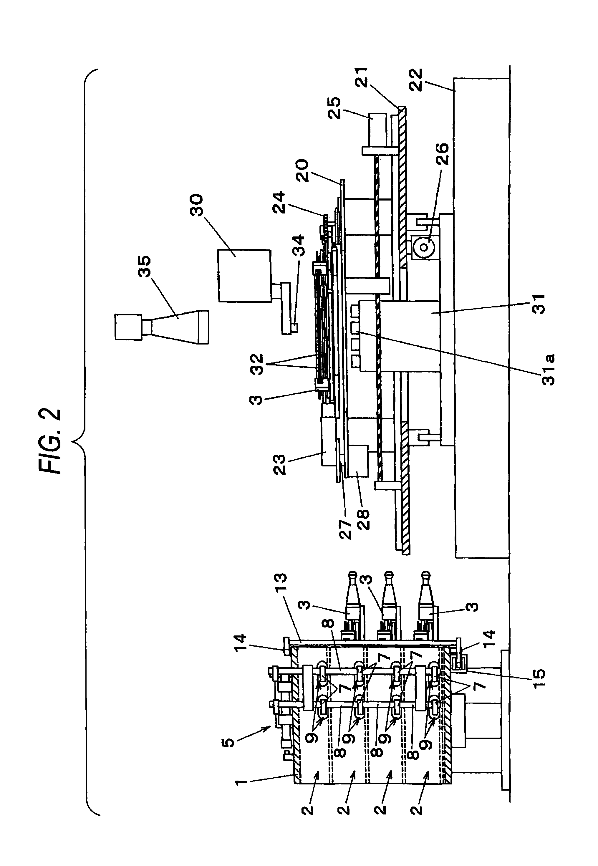
[0035]Now, an exemplary embodiment of the present invention will be described below by referring to the drawings. FIG. 1 is a plan view of an automatic pallet exchange device of the exemplary embodiment of the present invention. FIG. 2 is a side view of the automatic pallet exchange device of the exemplary embodiment of the present invention. FIG. 3 is an explanatory view of a pallet positioning mechanism. FIG. 4 is an explanatory view of a mechanism for fixing a pallet by a first pallet fixing part. FIG. 5 is a plan view of a wafer ring. FIG. 6 is a plan view of a pallet rotating part. FIG. 7 is a plan view of a base part of the pallet. FIG. 8 is a plan view of an entire part of the pallet. FIG. 9 is an explanatory view of a mechanism for attaching the wafer ring to the pallet rotating part. FIG. 10 is an explanatory view of a mechanism for attaching the pallet rotating part to the base of the pallet. FIG. 11 is an explanatory view of a mechanism for regulating the rotation of the ...


PUM

PropertyMeasurementUnit
Timeaaaaaaaaaa
Diameteraaaaaaaaaa

Abstract

An automatic pallet exchange device includes: a pallet magazine 1 that accommodates a plurality of pallets 3 respectively having a plurality of horizontally extending protrusions 16 so as to be taken in and out in horizontal directions; a pallet fixing part 23 that allows the plurality of protrusions 16 to be engaged with a plurality of depression parts 17 to horizontally fix the pallet 3 and a pallet fixing table 20 on which the pallet fixing part 23 is arranged. The pallet 3 horizontally fixed by the pallet fixing part 23 is horizontally turned and horizontally moved to exchange the pallets 3 between the pallet fixing table 20 and the pallet magazine 1.

Description

BACKGROUND OF THE INVENTION[0001]1. Field of the Invention[0002]The present invention relates to a device for automatically exchanging a pallet that supplies a die used in a die-bonding device.[0003]2. Description of the Related Art[0004]A die-bonding device carries out a bonding operation for mounting a die peeled off from a wafer sheet on a board by a thermal compression and bonding. Since the wafer sheet is rich in its flexibility and inconveniently hardly treated as it is, in the bonding device, the wafer sheet is handled under a state that the wafer sheet is mounted on an annular rigid member called a pallet. In patent literature 1, an example is disclosed in which a pallet is used in a bonding device. Herein, a plurality of pallets are previously accommodated in a pallet accommodation magazine so as to completely use a die of the pallet in use at present or replace the pallet by another pallet which is accommodated in the magazine when a different kind of die is desired to be ...

Claims


Application Information

Patent Timeline
IPC IPC(8): B65G59/02B23Q3/00
CPCB23Q7/1431Y10T29/5196
Inventor TAKANAMI, YASUO
Owner PANASONIC CORP
Why Eureka
Try Eureka