Fuel cell stack and fuel cell using the same

a fuel cell and stack technology, applied in the direction of fuel cells, fuel cell components, fuel cell grouping, etc., can solve the problems of requiring long-time durability and safety, accelerate technology development, etc., and achieve the effect of reducing the volume of the fuel cell stack as a whole and the size of the fuel cell stack

Inactive Publication Date: 2010-07-08
PANASONIC CORP
View PDF7 Cites 8 Cited by
  • Summary
  • Abstract
  • Description
  • Claims
  • Application Information

AI Technical Summary

Benefits of technology

[0006]The fuel cell stack of the present invention includes a membrane electrode assembly, a pair of end plates, and a first plate spring. The membrane electrode assembly and the end plates form a unit cell of fuel cell. The membrane electrode assembly is formed by laminating an anode electrode, a cathode electrode, and an electrolyte membrane interposed between the anode and cathode electrodes. The end plates are disposed so as to sandwich the membrane electrode assembly from both sides in the laminating direction of the membrane electrode assembly. The first plate spring tightens the membrane electrode assembly and the end plates in the laminating direction. The first plate spring includes two arm sections for pressing the end plates and a connecting section for connecting the two arm sections so as to have a C-shaped cross-section. In this way, by fastening the unit cell of fuel cell using the first plate spring having a C-shaped cross-section, the fuel cell stack can be reduced in size as compared with the case where the fuel cell stack is fastened with bolts and nuts. Furthermore, the unit cell of fuel cell can be fastened uniformly in the planer direction of the membrane electrode assembly, as well as in the center portion. Thus, according to the present invention, the occupied volume of the fuel cell stack as a whole can be reduced and the unit cell of fuel cell can be fastened uniformly.

Problems solved by technology

Furthermore, technology development has been accelerated in not only secondary batteries used for small consumer goods but also large secondary batteries for electric power storages and electric vehicles, which require long-time durability and safety.

Method used


Image

  • Fuel cell stack and fuel cell using the same
  • Fuel cell stack and fuel cell using the same
  • Fuel cell stack and fuel cell using the same

Examples


Embodiment Construction

[0015]Hereinafter, the exemplary embodiments of the present invention are described with reference to drawings in which a direct methanol fuel cell (DMFC) is taken as an example. Note here that the present invention is not limited to the embodiments mentioned below as long as it is based on the basic features described in the description.

Exemplary Embodiment

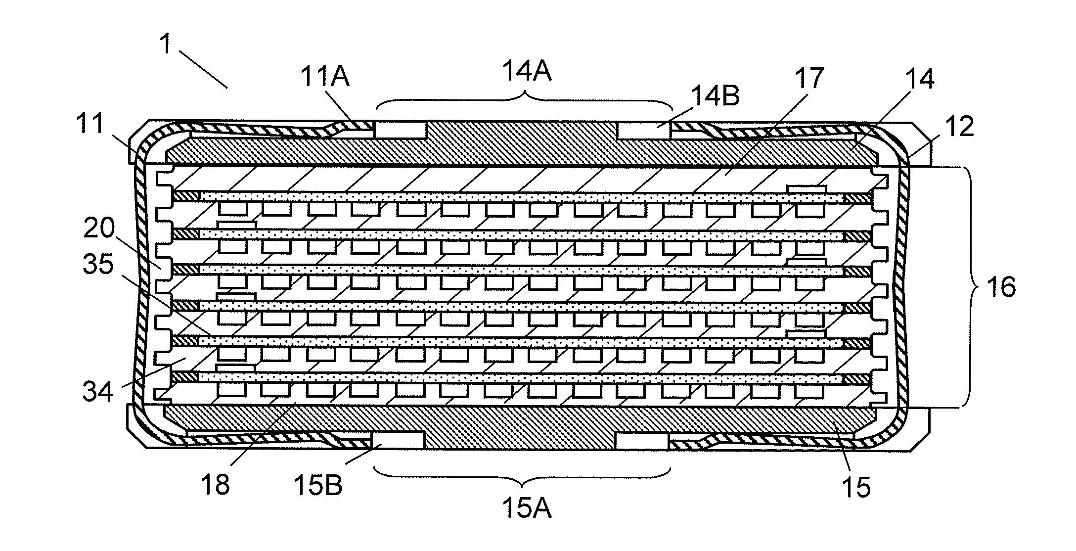
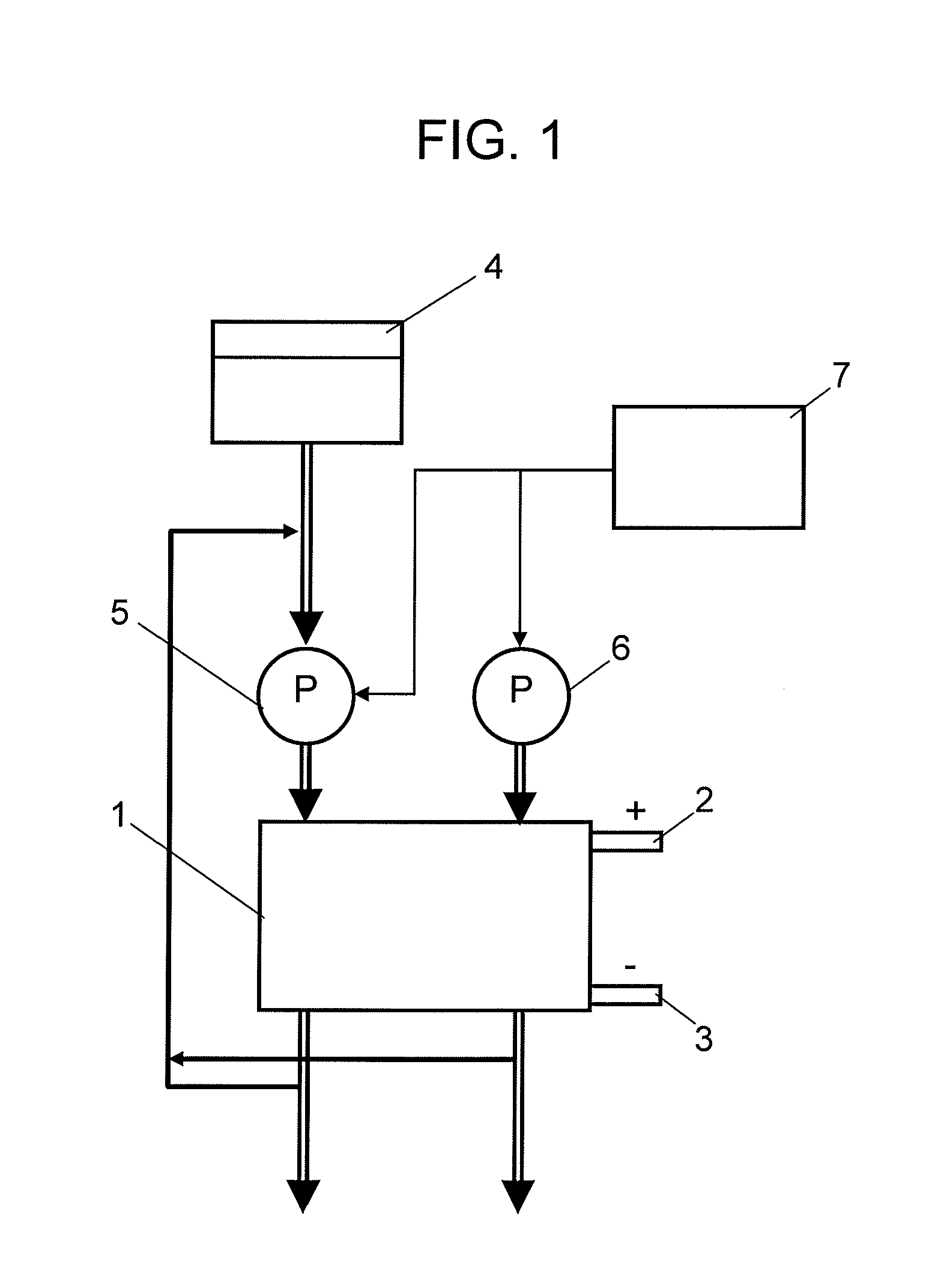
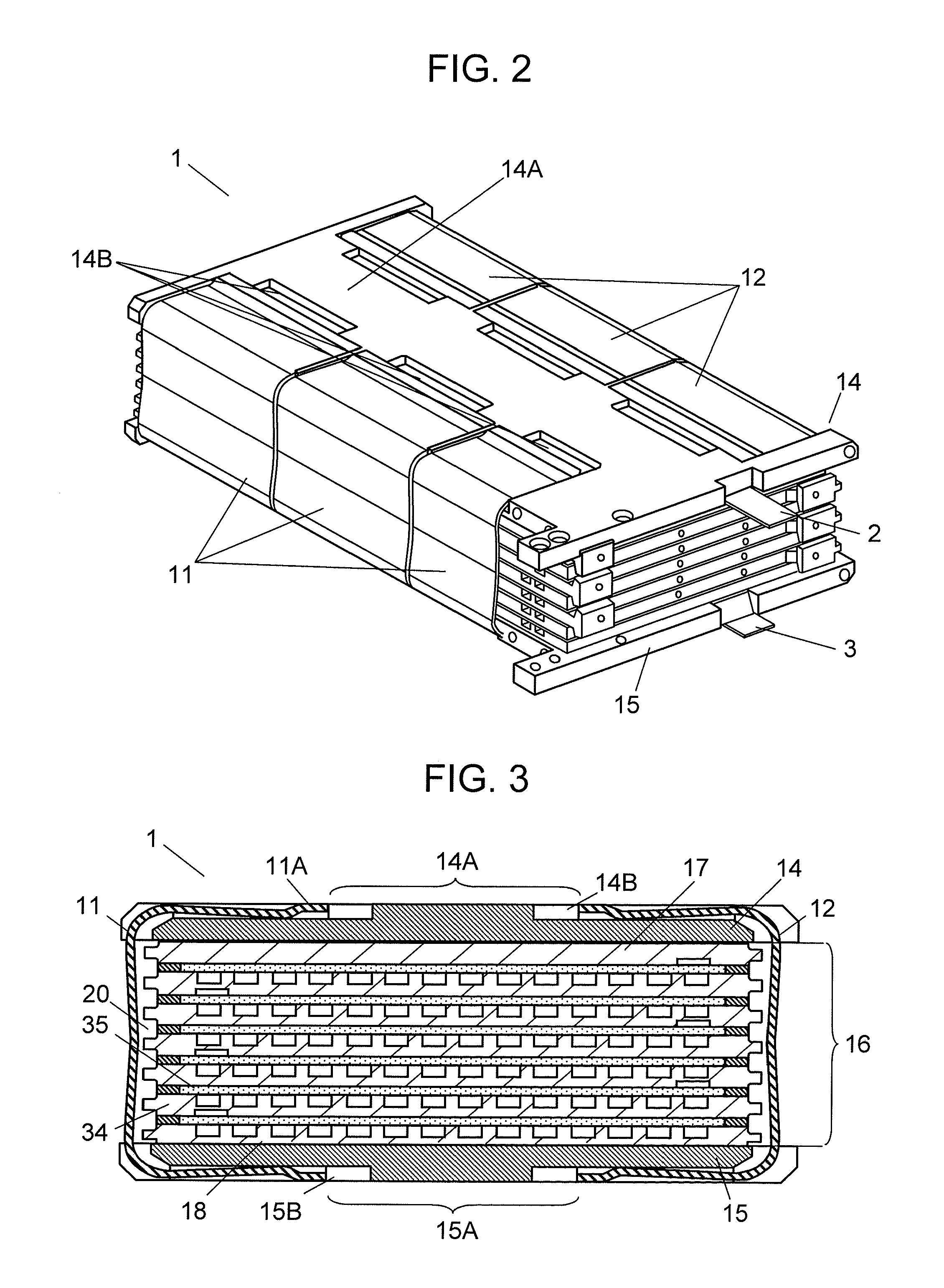
[0016]FIG. 1 is a block diagram showing a configuration of a fuel cell in accordance with the exemplary embodiment of the present invention. FIGS. 2 and 3 are a perspective view and a sectional view showing a fuel cell stack in accordance with the exemplary embodiment of the present invention. FIG. 4 is an enlarged sectional view showing a schematic configuration of a principal part of the fuel cell stack.

[0017]The fuel cell includes fuel cell stack 1, fuel tank 4, fuel pump 5, air pump 6, and controller 7. Fuel cell stack 1 has an electricity generation section, and outputs the generated electric power from positive-electrode te...


PUM

PropertyMeasurementUnit
frictionaaaaaaaaaa
shapeaaaaaaaaaa
energy densityaaaaaaaaaa

Abstract

In a fuel cell stack, a cell stack formed by laminating a membrane electrode assembly and a separator and sandwiching them from the both sides in the laminating direction with a pair of end plates is fastened by being tightened in the laminating direction with a first plate spring. The first plate spring includes two arm sections for pressing the pair of end plates and a connecting section connecting the arm sections, and has a C-shaped cross-section.

Description

TECHNICAL FIELD[0001]The present invention relates to a fuel cell stack and a fuel cell using the same. More particularly, it relates to a structure for fastening a fuel cell stack.BACKGROUND ART[0002]Recently, with the rapid widespread of portable and cordless electronic devices, as driving power sources for such devices, small, lightweight and high energy density secondary batteries have been increasingly demanded. Furthermore, technology development has been accelerated in not only secondary batteries used for small consumer goods but also large secondary batteries for electric power storages and electric vehicles, which require long-time durability and safety. In addition, much attention has been paid to fuel cells enabling long-time continuous use with fuel supplied, rather than secondary batteries that need charging.[0003]A fuel cell includes a fuel cell stack including a cell stack, a fuel supplying section for supplying fuel to the cell stack, and an oxidizing agent supplyin...

Claims


Application Information

Patent Timeline
Patent Type & Authority Applications(United States)
IPC IPC(8): H01M8/24
CPCH01M4/8657H01M8/0245H01M8/0247Y02E60/50H01M8/2455H01M8/248H01M8/1011
Inventor KOZU, KATSUMIFUKUDA, SHINSUKE
Owner PANASONIC CORP
Why Eureka
Try Eureka