Method for physiologic control of a continuous flow total artificial heart

a total artificial heart and physiologic control technology, applied in the field of artificial hearts, to achieve the effect of reducing the peak motor speed

Active Publication Date: 2010-07-08
THE CLEVELAND CLINIC FOUND
View PDF33 Cites 13 Cited by
  • Summary
  • Abstract
  • Description
  • Claims
  • Application Information

AI Technical Summary

Benefits of technology

[0008]According to another aspect of the invention, a method is provided for controlling a pump including a electrical motor coupled to a rotor which carries first and second impellers at opposite ends thereof. The method includes: (a) driving the rotor using the motor, so as to circulate fluid from the first impeller through a first fluid circuit, the second impeller, a second fluid circuit, and back to the first impeller; (b) modulating the speed of the rotor to generate a pulsatile flow; (c) monitoring a motor parameter indicative of suction or rubbing; and (d) in response to an indication of suction or rubbing, reducing the peak motor speed.

Problems solved by technology

Heart transplant is a course of action for patients with end stage heart failure, a leading cause of premature death.

Method used


Image

  • Method for physiologic control of a continuous flow total artificial heart
  • Method for physiologic control of a continuous flow total artificial heart
  • Method for physiologic control of a continuous flow total artificial heart

Examples


Embodiment Construction

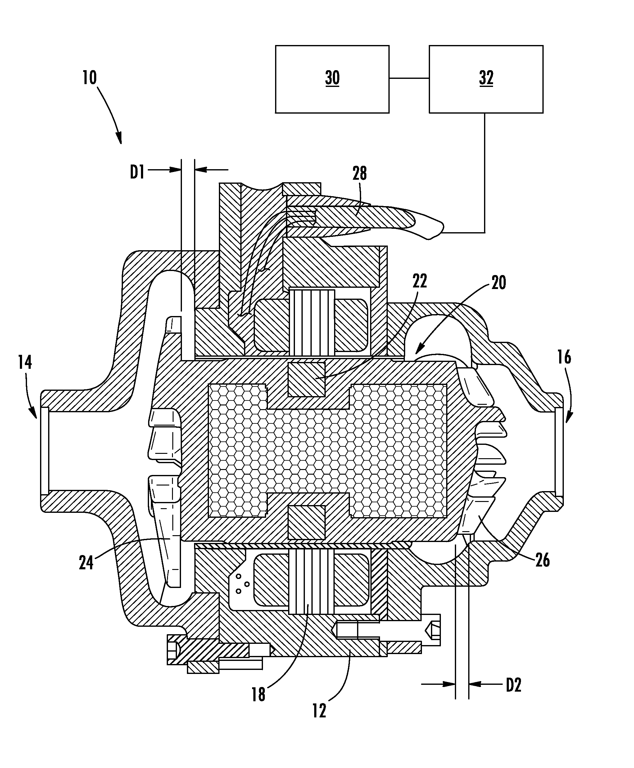
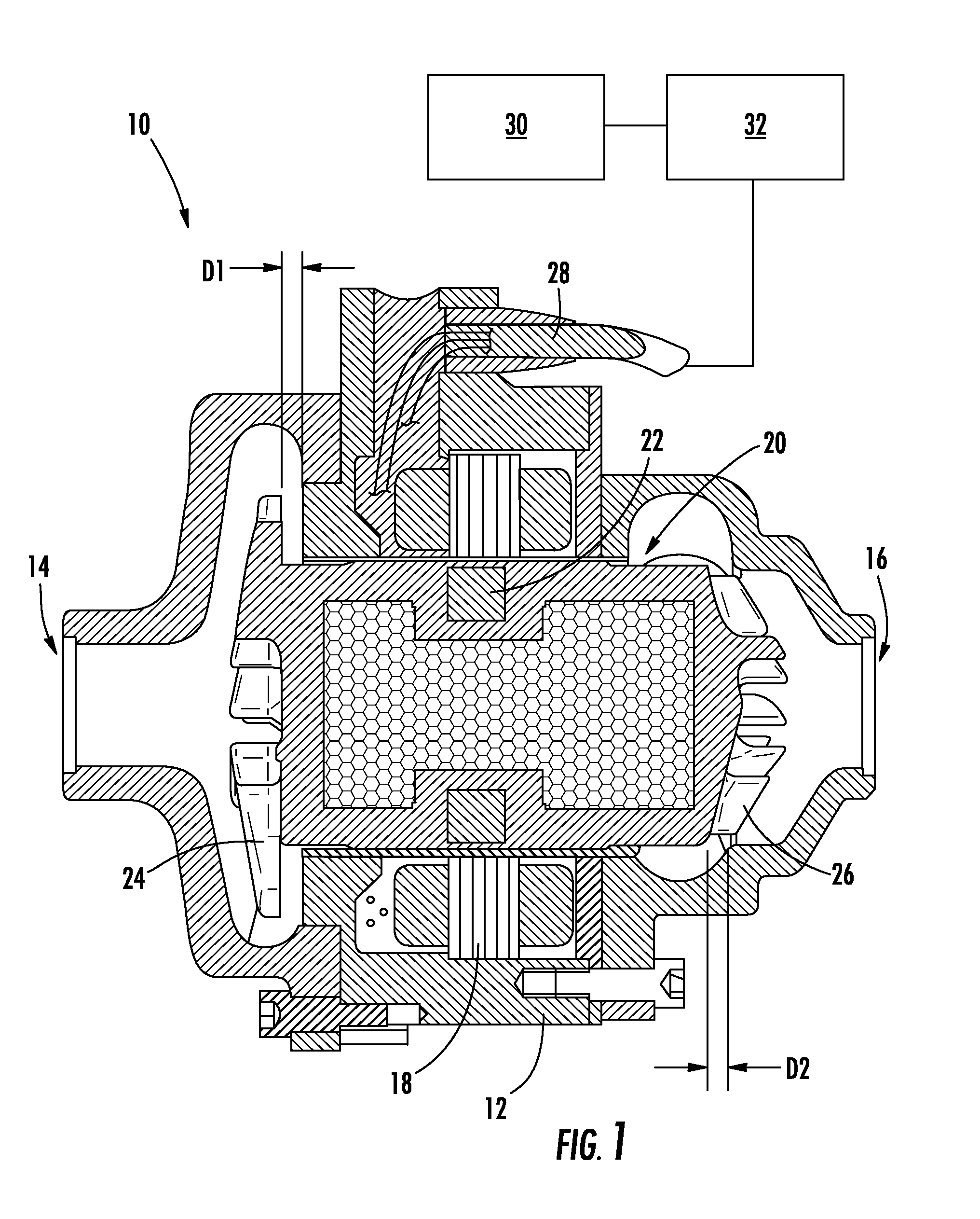
[0021]Referring to the drawings wherein identical reference numerals denote the same elements throughout the various views, FIG. 1 depicts a continuous flow total artificial heart 10 used to temporarily or permanently support an human patient. The artificial heart 10 includes a hollow housing 12 with opposed left and right inlets 14 and 16. An electrical stator 18 comprising a plurality of coil windings is disposed in the housing 12. While a total artificial heart 10 is used as an illustrative example, the principles of the present invention are equally applicable to other kinds of mechanical configurations and pumps, for example ventricular assist devices.

[0022]A rotor 20 is disposed inside the stator 18. The rotor 20 includes a magnet assembly 22 comprising one or more permanent magnets arranged in an annular configuration. A left impeller 24 comprising an annular array of vanes is carried at the left end of the rotor 20 adjacent the left inlet 14. A right impeller 26 comprising a...


PUM


Abstract

A method is provided of controlling a pump including a electrical motor coupled to a rotor which carries first and second impellers at opposite ends thereof. The method includes: (a) driving the rotor using the motor, so as to circulate fluid from the first impeller through a first fluid circuit, the second impeller, a second fluid circuit, and back to the first impeller; (b) determining a resistance of the first fluid circuit, based on a first motor parameter; (c) determining a flow rate through the first fluid circuit based on a second motor parameter; and (d) varying at least one operational parameter of the pump so as to maintain a predetermined relationship between the flow rate and the resistance of the first fluid circuit.

Description

BACKGROUND OF THE INVENTION[0001]This invention relates generally to artificial hearts, and more particularly to methods of control therefor.[0002]Heart transplant is a course of action for patients with end stage heart failure, a leading cause of premature death. Because of the unavailability of donor hearts, electromechanical blood pumping systems are being developed and are increasingly coming into use. These devices can provide a bridge to transplant, bridge to recovery, or as a permanent treatment for patients who may not receive a donor heart. Most such patients will be treated with a ventricular assist device (“VAD”), which draws blood from the left or right ventricle, and discharges to the aorta or pulmonary artery, respectively. Some patents require a total artificial heart (TAH) as either a bridge to transplant, or as a permanent therapy.[0003]One known type of TAH is a continuous flow total artificial heart (CFTAH) which includes two centrifugal pumps on one rotor support...

Claims


Application Information

Patent Timeline
Patent Type & Authority Applications(United States)
IPC IPC(8): A61M31/00
CPCA61M1/101A61M1/1086A61M1/12A61M1/1031F04D15/0066A61M1/1005A61M1/1001A61M2205/3334A61M60/562A61M60/422A61M60/546A61M60/216A61M60/196A61M60/523
Inventor HORVATH, DAVIDMASSIELLO, ALEXGOLDING, LEONARD A. R.KUBAN, BARRY
Owner THE CLEVELAND CLINIC FOUND
Why Eureka
Try Eureka