Solar energy-collecting architectural enclosure panel and walkable solar energy-collecting roof

Inactive Publication Date: 2010-07-15
PETRA INVENTUM
View PDF36 Cites 59 Cited by
  • Summary
  • Abstract
  • Description
  • Claims
  • Application Information

AI Technical Summary

Benefits of technology

[0009]With this construction, the mentioned distance between said leak-tight joint line forming the closed perimeter and the opposite longitudinal edges of the outer and inner plates provides a passage free of hollow conformations with a sufficient width to allow placing at least one foot, while at the same time the mentioned mechanical connection between the outer and inner plates ensures that the two outer and inner plates both act together as structural elements to withstand, for example, at least the weight of an operator walking on solar energy-collecting architectural enclo

Problems solved by technology

Firstly, a roof formed by a plurality of such collectors would not be walkable, for example, for maintenance, due to the brittleness of the panes of glass forming the air chamber on the outer surface.
Even if the panes of glass were uninstalled before accessing the roof, an operator would be obliged to step on the hollow conformations forming the circuit for the heat-carrying fluid with the risk of crushing them, since said conformations occupy the entire extension of the outer plate between its longitudinal edges.
In addition, supposing that panes of glass that are strong enough to be walkable are used for the outer air chamber, the roof would have practical viability problems due to the additional weight and to the high cost of such walkable panes of glass.
Secondly, the solar collector of patent U.S. Pat. No. 4,010,733 does not have transverse reinforcing members to ensure the walkability of the roof, and furthermore, the laye

Method used


Image

  • Solar energy-collecting architectural enclosure panel and walkable solar energy-collecting roof
  • Solar energy-collecting architectural enclosure panel and walkable solar energy-collecting roof
  • Solar energy-collecting architectural enclosure panel and walkable solar energy-collecting roof

Examples


Example

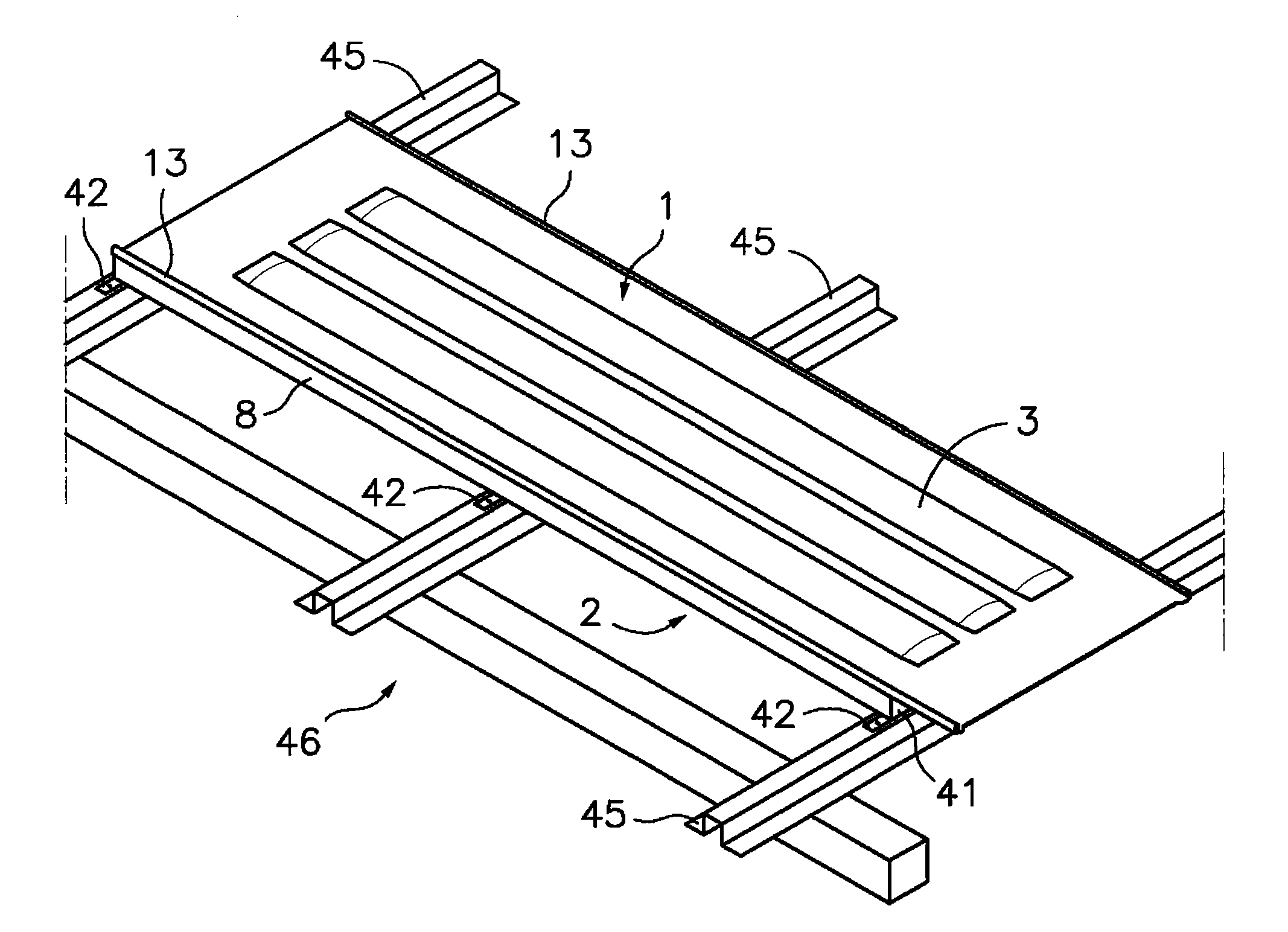
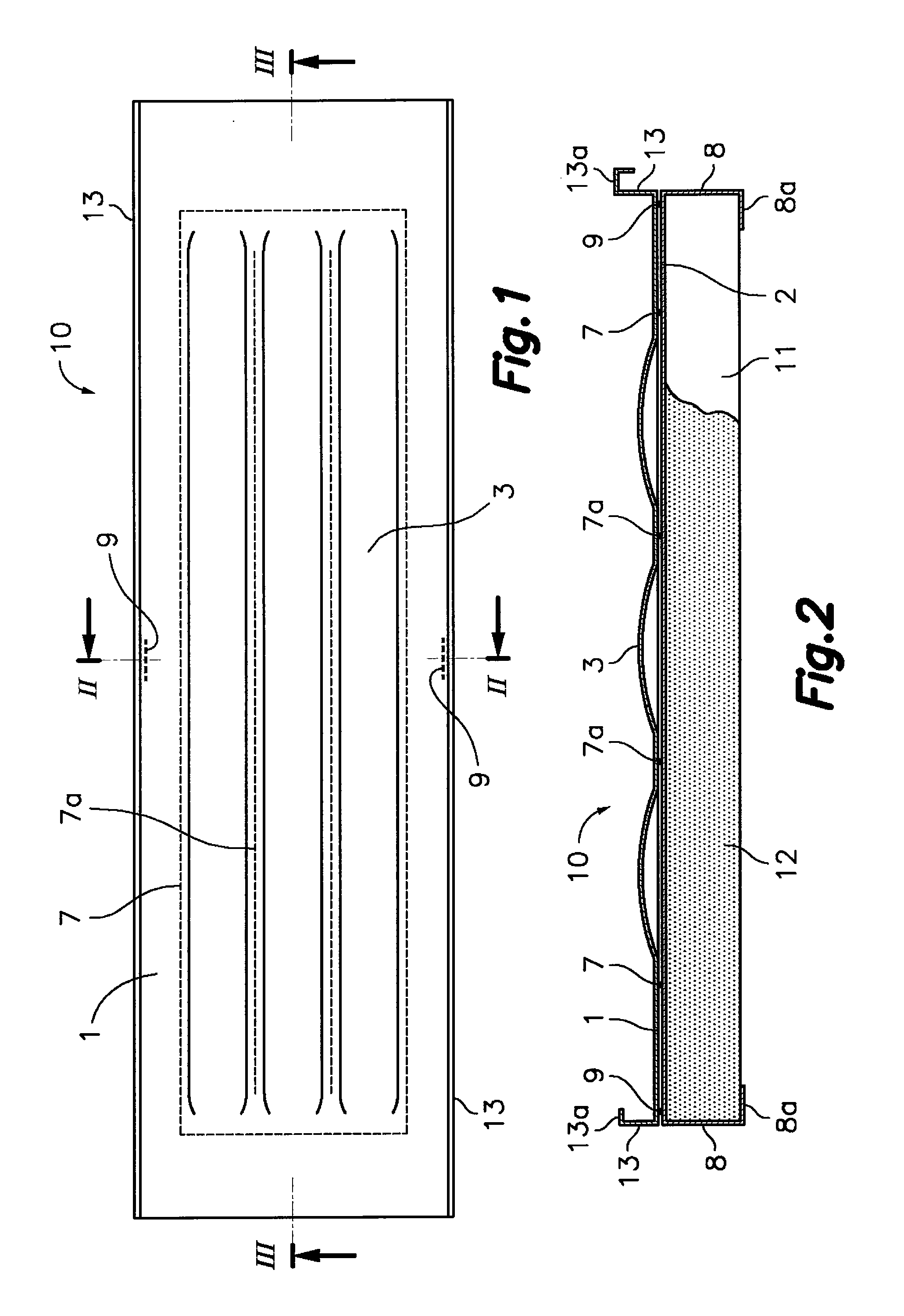
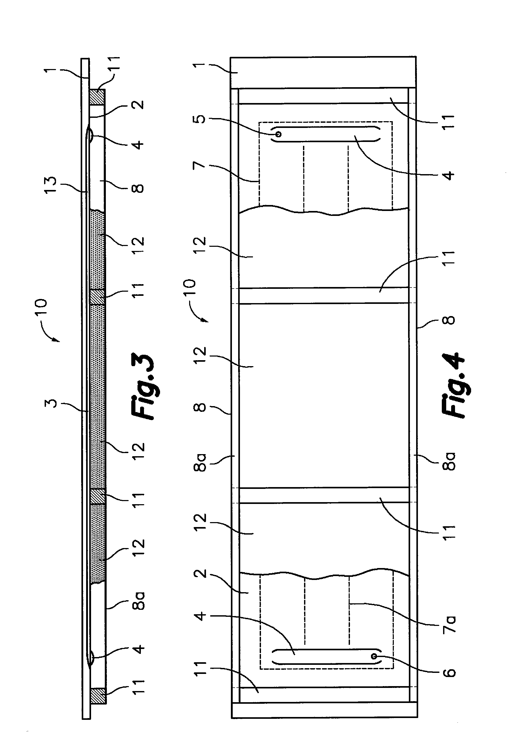
[0041]With reference first to FIGS. 1 to 4, the solar energy-collecting architectural enclosure panel according to the first aspect of the present invention is formed from an outer plate 1 and an inner plate 2 which are mutually facing and joined by a leak-tight joint line along a closed perimeter 7, which is separated at a predetermined distance from perimetric edges of said outer and inner plates 1, 2. The outer plate 1 has outwardly projecting hollow conformations 3 (FIGS. 1, 2 and 3) with a longitudinal configuration and the inner plate 2 has inwardly projecting hollow conformations 4 (FIGS. 3 and 4) with a transverse configuration. The mentioned hollow conformations 4 of the inner plate 2 are facing one another at the ends of the hollow conformations 3 of the outer plate 1 such that between both they form a circuit for a heat-carrying fluid within said closed perimeter 7. The mentioned circuit has an inlet 5 and an outlet 6, for example, in the hollow conformations 4 of the inn...


PUM


Abstract

The solar energy-collecting architectural enclosure panel includes outer and inner plates which are mutually facing and joined by a leak-tight joint along a closed perimeter separated at a distance from perimetric edges of the panel. The outer and inner plates include within the closed perimeter hollow conformations to form a circuit for a heat-carrying fluid with an inlet and an outlet. Adjacent to opposite longitudinal edges of the outer plate there are first longitudinal stiffening configurations and adjacent to opposite longitudinal edges of the inner plate there are second longitudinal stiffening configurations configured to rest on transverse elements of a structure. The outer and inner plates are furthermore joined by a mechanical connection in expected maximum bending stress areas adjacent to the opposite longitudinal edges of the outer and inner plates.

Description

TECHNICAL FIELD [0001]The present invention generally relates to a solar energy-collecting architectural enclosure panel, applicable to a roof and to a façade, and more particularly to a solar energy-collecting architectural enclosure panel formed from two shaped plates facing one another, joined along a leak-tight joint line and provided with additional mechanical connections to form a panel suitable for advantageously forming part of a walkable solar energy-collecting roof, although it is also suitable for other types of enclosures.[0002]The present invention also relates to a walkable solar energy-collecting roof provided with an air chamber at the lower part, which can be closed or communicated with the outside or with an inner heating air pipeline of a building in which the cover is installed.BACKGROUND OF THE INVENTION[0003]International patent application WO2004083556, the inventor of which is the current applicant, discloses a multifunctional element which is used to form a ...

Claims


Application Information

Patent Timeline
IPC IPC(8): E04D13/18F16B11/00F24S10/50
CPCE04D3/30Y10T403/477E04D3/357E04D3/365E04D13/1618E04D13/1637E04D13/17F24J2/045F24J2/204F24J2/5205F24J2/5243F24J2/5245F24J2/5262F24J2002/0053F24J2002/0061Y02B10/20Y02E10/44Y02E10/47E04D3/351E04D3/361F24S2080/09F24S25/61F24S2020/12F24S25/30F24S20/67F24S25/33F24S25/60F24S2025/6002F24S2020/13F24S10/503F24S25/67Y02A30/60F24S80/00E04D3/24F24S25/00
Inventor GARCIA CORS, JOSEP
Owner PETRA INVENTUM
Why Eureka
Try Eureka