Traversing fuel nozzles in cap-less combustor assembly

a fuel nozzle and combustor technology, applied in liquid fuel engines, lighting and heating apparatus, machines/engines, etc., can solve the problems of nozzle-to-nozzle flame front interaction detrimental, emissions penalty, and non-adjustable features,

Inactive Publication Date: 2010-07-15
GENERAL ELECTRIC CO
View PDF5 Cites 35 Cited by
  • Summary
  • Abstract
  • Description
  • Claims
  • Application Information

AI Technical Summary

Problems solved by technology

Thus, conditions within the combustion system are typically “staged” to create local zones of stable combustion despite the fact that bulk conditions may place the design outside its operational limits (i.e., emissions, flammability, etc.).
However, these features tend to be either non-adjustable or can only be exercised at the expense of another fundamental boundary such as emissions.
Most combustor designs have a means of staging the fuel flow (commonly referred to as a “fuel split”) but this creates an emissions penalty.
If instead the nozzles are in distinct axial locations, then the main effect is to change the convective times. A

Method used


Image

  • Traversing fuel nozzles in cap-less combustor assembly
  • Traversing fuel nozzles in cap-less combustor assembly
  • Traversing fuel nozzles in cap-less combustor assembly

Examples


Embodiment Construction

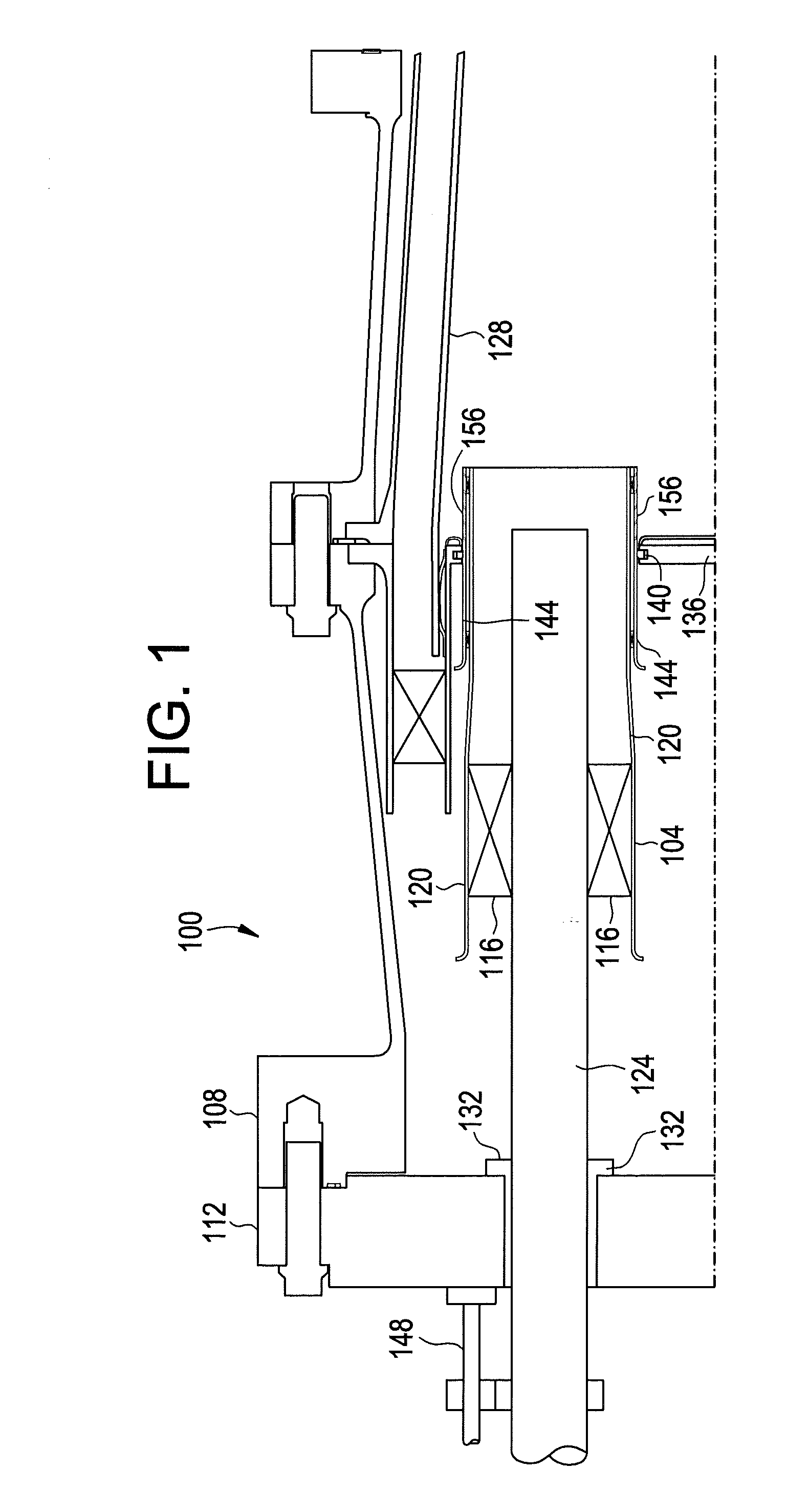
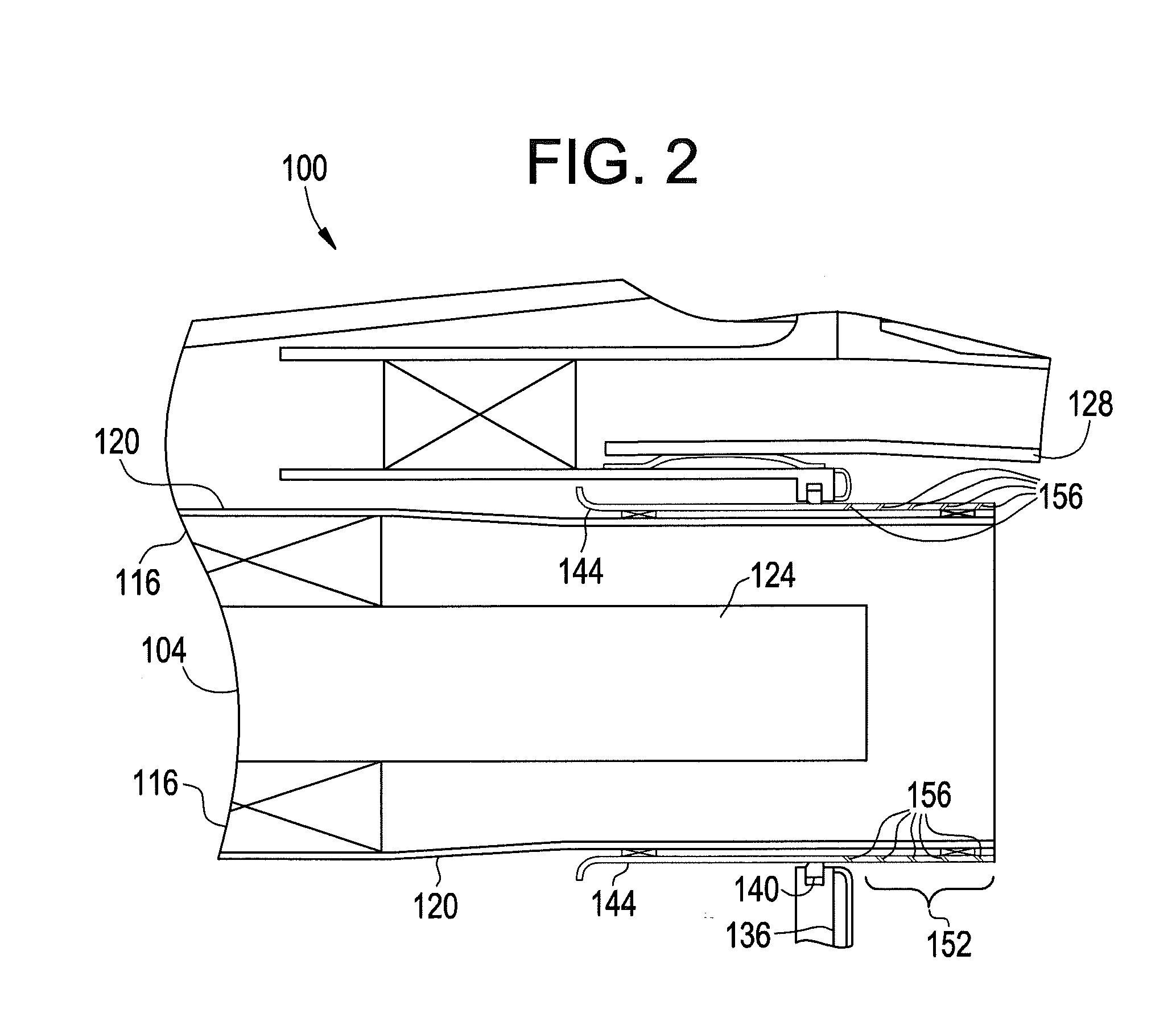
[0015]Referring to FIGS. 1 and 2, a combustor 100 for a gas turbine includes a plurality of fuel nozzle assemblies 104, one of which is shown in the embodiment of FIGS. 1 and 2. One or more of the plurality of fuel nozzle assemblies 104 may traverse axially back and forth according to embodiments of the invention. As shown in FIG. 1, the combustor 100 also includes a combustor case 108 and an end cover 112. Each of the fuel nozzle assemblies 104 may include a vane 116, an inner shroud 120, a center body 124, a liner 128, a seal assembly 132, a bulkhead / cap assembly 136, a seal 140, an outer shroud 144, and an actuator mechanism 148.

[0016]In accordance with one embodiment of the invention, the entire fuel nozzle assembly 104 may be moved or traversed axially. In accordance with another embodiment, only the center body 124 of the fuel nozzle assembly 104 may be moved axially. In addition, only one of the fuel nozzle assemblies 104 may be moved axially at any one time, or some combinat...


PUM


Abstract

A combustor includes a central fuel nozzle assembly and a plurality of outer fuel nozzle assemblies, each of the plurality of outer fuel nozzle assemblies having a center body and an outer shroud, the plurality of outer fuel nozzle assemblies being configured to abut one another in a surrounding relationship to the central cylinder such that no gaps are present between any two abutting ones of the plurality of outer fuel nozzle assemblies. One or more of the plurality of fuel nozzle assemblies may traverse axially back and forth according to embodiments of the invention.

Description

BACKGROUND OF THE INVENTION[0001]Premixed Dry Low NOx (DLN) combustion systems for heavy-duty gas turbines for both annular and can-annular designs arc based on fuel staging, air staging, or a combination of the two. This enables operation across a relatively wide range of conditions. The window for premixed combustion is relatively narrow when compared to the duty cycle of a modern gas turbine. Thus, conditions within the combustion system are typically “staged” to create local zones of stable combustion despite the fact that bulk conditions may place the design outside its operational limits (i.e., emissions, flammability, etc.).[0002]Additionally, staging affords an opportunity to “tune” the combustion system away from potentially damaging acoustic instabilities. Premixed systems may experience combustion “dynamics”. The ability to change the flame shape, provide damping, or stagger the convective time of the fuel to the flame front have all been employed as a means to attempt to...

Claims


Application Information

Patent Timeline
IPC IPC(8): F02C7/18F02C7/22F01D17/12
CPCF23R3/286F23C5/02F23C5/06F23R3/283
Inventor DAVIS, JR., LEWIS BERKLEYCITENO, JOSEPH VINCENTJOHNSON, THOMAS EDWARDZIMINSKY, WILLY STEVE
Owner GENERAL ELECTRIC CO
Why Eureka
Try Eureka