Method for monitoring an engine starting system and engine including starting system monitor

a technology for starting systems and engines, applied in the direction of engine starters, electric control, machines/engines, etc., can solve problems such as stranded vehicles and delay in delivery of goods

Active Publication Date: 2010-07-15
VOLVO LASTVAGNAR AB
View PDF19 Cites 29 Cited by
  • Summary
  • Abstract
  • Description
  • Claims
  • Application Information

AI Technical Summary

Benefits of technology

[0004]Diagnostic methods have been developed to determine a battery's health. The known methods do an adequate job for this one component but other factors and components also play roles in proper starting. The inventor has recognized that it is desirable to provide a method that can coordinate sensors that can be provided on the engine and / or vehicle to track the starting performance and at least assist in diagnosis of root causes of the various aspects involved in starting an engine, particularly a diesel engine.
[0005]According to an aspect of the present invention, a method of monitoring an engine starting system in an engine is provided, the engine starting system comprising a charging system, a battery, a starter, a flywheel, and a controller. According to the method a charging system voltage is monitored and the charging system voltage is compared with predetermined charging system voltage values. Voltage of the battery is monitored and battery voltage is compared with predetermined battery voltage values. A signal to an operator is provided if one or more of the charging system voltage and the battery voltage are outside of predetermined ranges for the one or more of the charging system voltage and the battery voltage.

Problems solved by technology

The fail mode of a battery is often such that it does not give obvious clues to the operator until it malfunctions.
A faulty battery often means the vehicle is stranded prior to completing its mission.
In commercial applications this results in delaying delivery of goods.

Method used


Image

  • Method for monitoring an engine starting system and engine including starting system monitor
  • Method for monitoring an engine starting system and engine including starting system monitor
  • Method for monitoring an engine starting system and engine including starting system monitor

Examples


Embodiment Construction

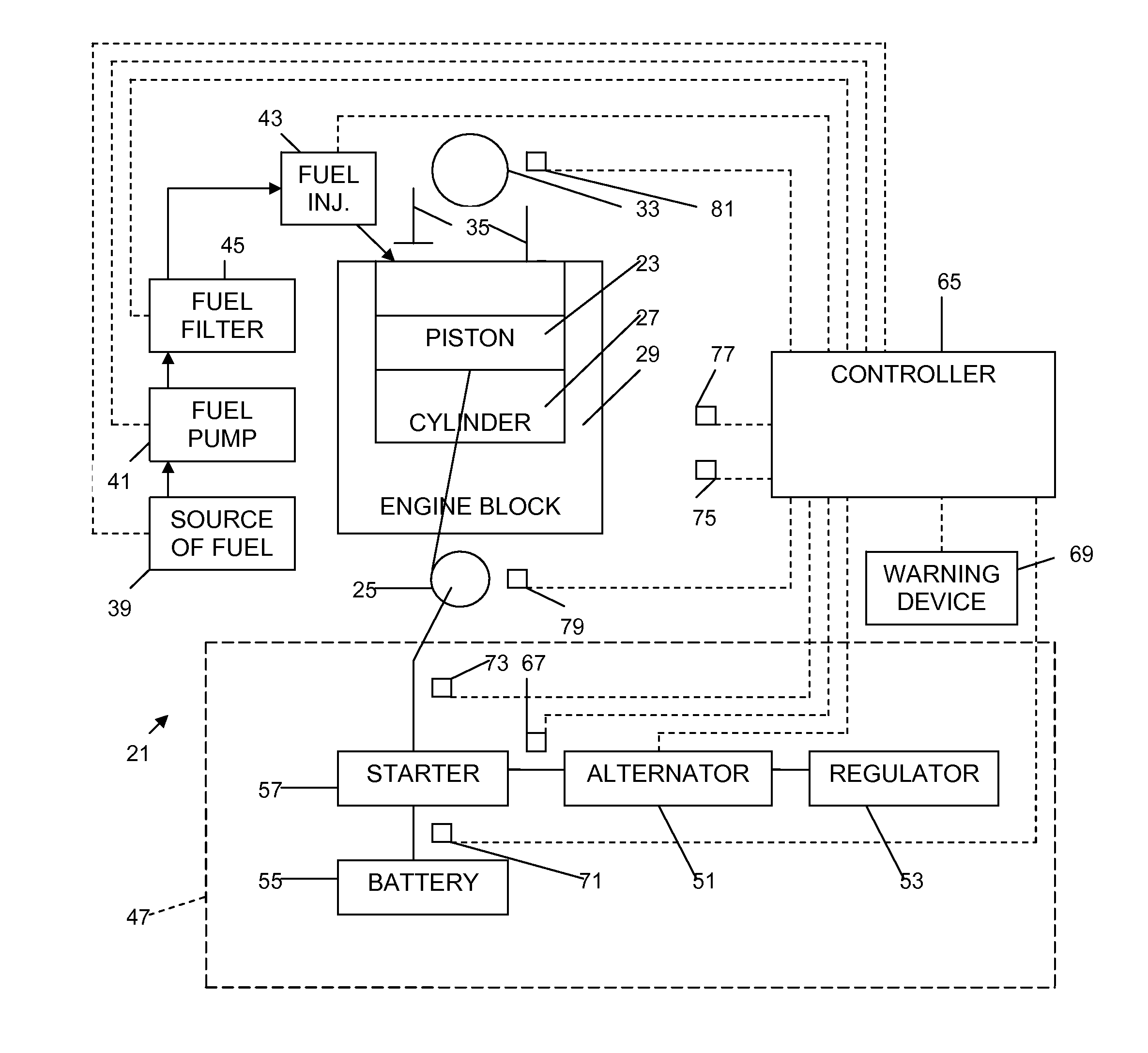
[0015]An engine 21 according to an aspect of the present invention is shown schematically in FIG. 1. The engine 21 comprises a piston 23 attached to a crankshaft 25, the piston moving in a cylinder 27 in the engine block 29 during combustion of fuel in the cylinder and thereby turning the crankshaft. A flywheel (not shown) is attached to the crankshaft 25, and a camshaft 33 can be driven by the crankshaft and opens and closes intake and exhaust valves 35 on the cylinder. A fuel system is provided and includes a source of fuel 39, a fuel pump 41, fuel injectors 43 for injecting fuel into the cylinders, and a fuel filter 45 for filtering the fuel prior to injection.

[0016]A starting system 47 for the engine 21 includes a charging system, which can include an alternator 51 having a regulator 53, a battery 55, a starter 57, which typically includes a starter motor with a starter gear adapted to mesh with a ring gear on the crankshaft 25 and turn the crankshaft under power from the batter...


PUM


Abstract

In a method of monitoring an engine starting system in an engine, the engine starting system includes a charging system, a battery, a starter, a flywheel, and a controller. The controller and monitors can monitor components and systems associated with starting of an engine, such as engine or cranking speed, power cylinder unit compression, injection timing, and proper fuel delivery to predict and/or diagnose problems. For example, a charging system voltage is monitored and the charging system voltage is compared with predetermined charging system voltage values. Voltage of the battery is monitored and battery voltage is compared with predetermined battery voltage values. A signal to an operator is provided if one or more of the charging system voltage and the battery voltage are outside of predetermined ranges for the one or more of the charging system voltage and the battery voltage.

Description

BACKGROUND AND SUMMARY[0001]The present invention relates to a method for monitoring an engine starting system and an engine including a starting system monitor.[0002]While an important application for the method and engine according to aspects of the present invention is in motor vehicles, such as truck diesel engines, it will be appreciated that the present invention has applications in engines for other uses, as well. Four of the more important requirements to start an engine are engine or cranking speed, power cylinder unit compression, injection timing, and proper fuel delivery.[0003]A great deal of work has already been done to ascertain the health of an engine battery. The fail mode of a battery is often such that it does not give obvious clues to the operator until it malfunctions. This key component supplies the electrical power required for normal operation of a vehicle. A faulty battery often means the vehicle is stranded prior to completing its mission. In commercial app...

Claims


Application Information

Patent Timeline
Patent Type & Authority Applications(United States)
IPC IPC(8): F02N11/08H02J7/04
CPCF02D41/062F02D41/22F02N11/10H02J7/1461F02P5/1506G01R31/006F02N2300/102F02N11/108F02N2200/044F02N2200/063H02J7/0048H02J7/005H02J7/14
Inventor DOUB, JOHN ELVIN
Owner VOLVO LASTVAGNAR AB
Why Eureka
Try Eureka