
Systems and methods for quantum receivers for target detection using a quantum optical radar

Active Publication Date: 2010-07-15
RAYTHEON BBN TECH CORP
View PDF2 Cites 11 Cited by
  • Summary
  • Abstract
  • Description
  • Claims
  • Application Information

AI Technical Summary

Benefits of technology

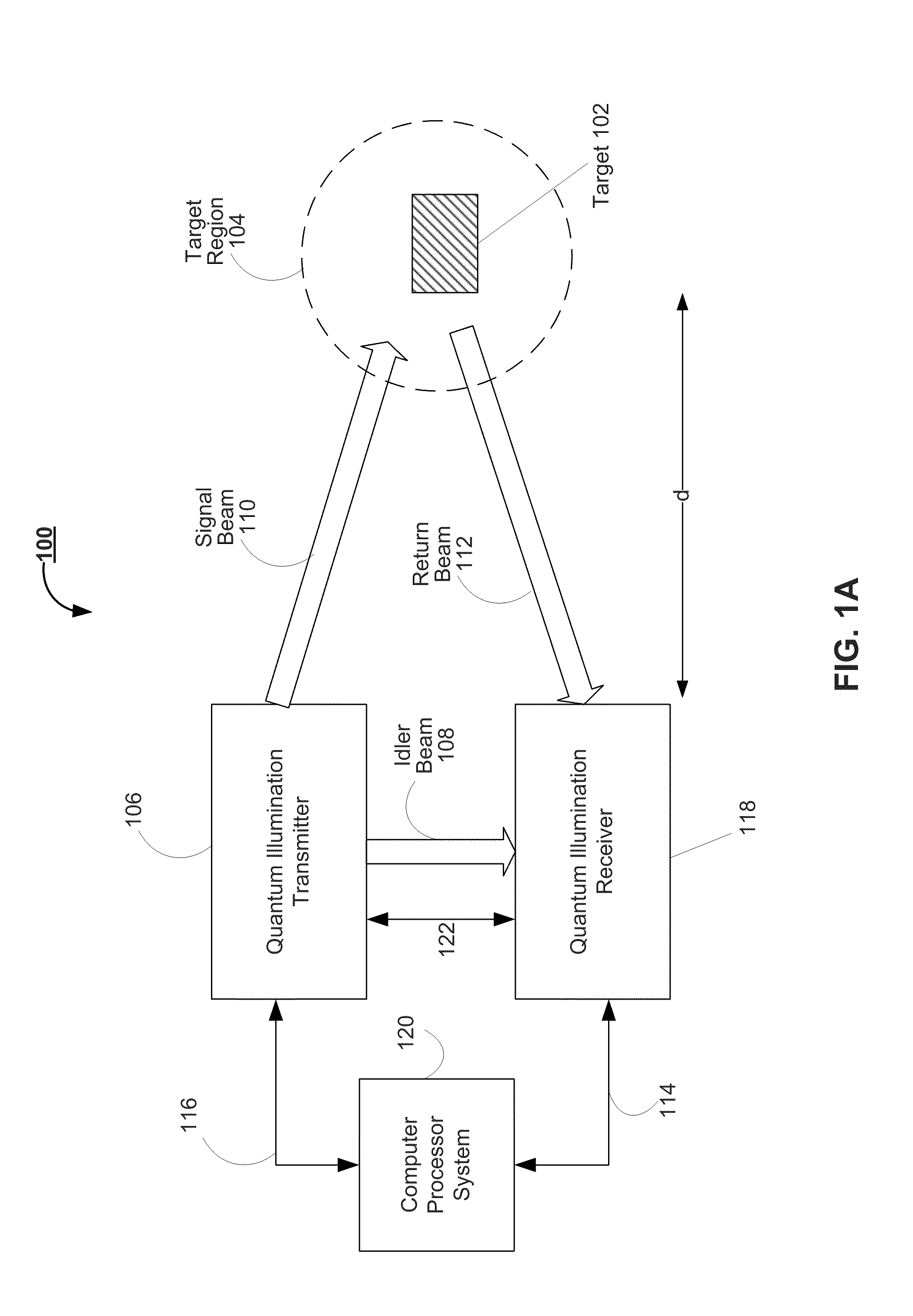
[0011]The systems and methods described herein in various embodiments provide for quantum illumination receivers that exploit entangled light transmitters to allow for improved target detection, imaging and range estimation performance, even under low signal-to-noise ratio operating conditions.

Problems solved by technology

However, this determination is not easily done in real world systems.
In addition, if the target region contains other light sources or thermal radiation (collectively referred to as “noise” sources), it may be very difficult to distinguish the component of the return signal containing light reflected off the target from that contributed by noise, because the return signal-to-noise ratio of the return light beam is very low.
However, no known detection system exists for realizing these theoretical predictions of enhancement.

Method used


Image

  • Systems and methods for quantum receivers for target detection using a quantum optical radar
  • Systems and methods for quantum receivers for target detection using a quantum optical radar
  • Systems and methods for quantum receivers for target detection using a quantum optical radar

Examples


Embodiment Construction

[0032]To provide an overall understanding of the invention, certain illustrative embodiments will now be described. However, it will be understood by one of ordinary skill in the art that the methods described herein may be adapted and modified as is appropriate for the application being addressed and that the systems and methods described herein may be employed in other suitable applications, and that such other additions and modifications will not depart from the scope hereof.

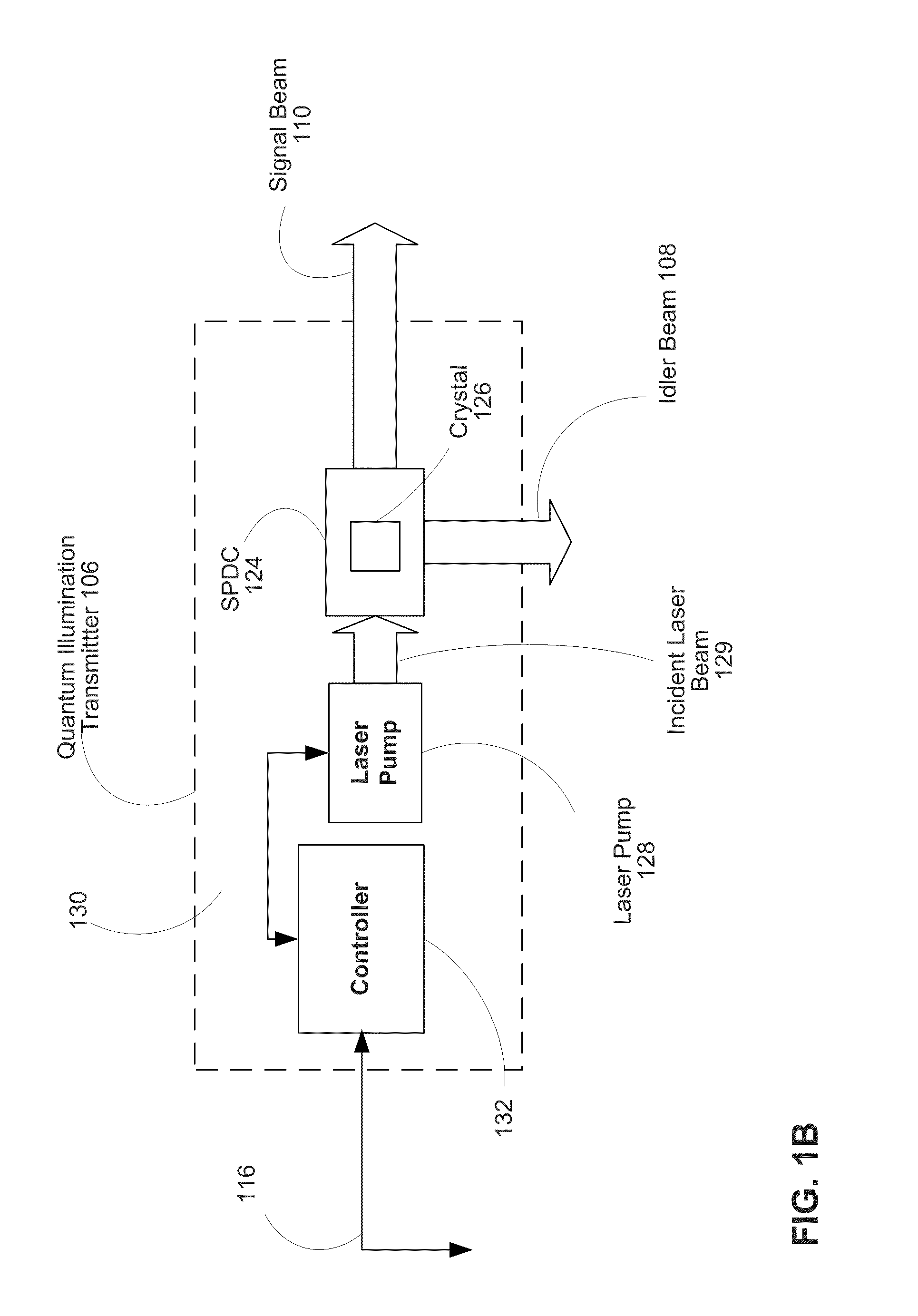
[0033]Recent research published in Science, Vol 321, Pages 1463-5, titled “Enhanced Sensitivity of Photodetection via Quantum Illumination,” and in Physical Review Letters 101, 253601 (2008), titled “Quantum Illumination with Gaussian States,” the contents of each of which are hereby incorporated herein in their entirety, suggests that with the use of quantum-mechanically entangled light to interrogate or illuminate distant objects, significant enhancements may be achieved over the user of unentangled / coheren...


PUM


Abstract

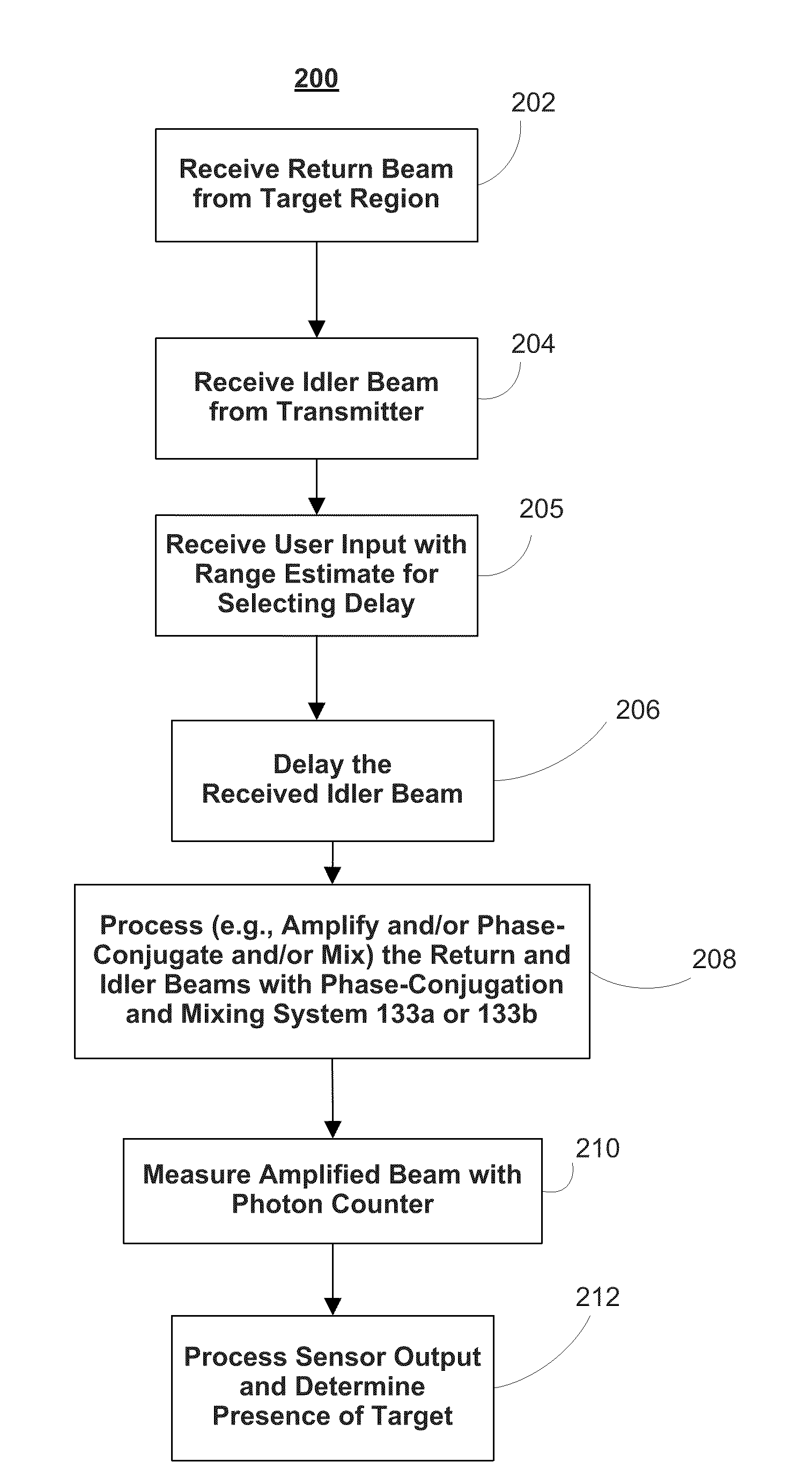
A quantum-illumination receiver is described comprising a phase-conjugation and mixing system for mixing and / or conjugating the idler beam from an entangled light transmitter and the return beam from the target to produce an output beam that is representative of the presence or absence of the target, a light beam collector for receiving a return light beam from the target region and directing the return light beam from a target region to the phase-conjugation and mixing system input, an optical input for receiving an idler light beam from a transmitter and directing the idler light beam from the transmitter to the phase-conjugation and mixing system, a sensor for measuring the output of the phase-conjugation and mixing system, and a processor to process the output of the sensor to make an determination about the presence of the target.

Description

CROSS-REFERENCE TO RELATED APPLICATIONS[0001]This application claims priority to U.S. Provisional Patent Application No. 61 / 144,003, filed Jan. 12, 2009, the contents of which are incorporated herein by reference in their entirety.GOVERNMENT CONTRACTS[0002]The U.S. Government has a paid-up license in this invention and the right in limited circumstances to require the patent owner to license others on reasonable terms as provided for by the terms of Contract No. FA8750-07-C-0206, awarded by the Defense Advanced Research Projects Agency.BACKGROUND OF THE INVENTION[0003]1. Field of the Invention[0004]The invention relates to the field of receivers for target detection, imaging, and range estimation. More particularly, this invention relates to the field of optical receivers for target detection, imaging, and range estimation.[0005]2. Background Information[0006]Optical or optoelectrical systems have long been used in various sensing applications, including but not limited to target de...

Claims


Application Information

Patent Timeline
IPC IPC(8): G01C3/08
CPCG01C3/08G01S17/08G01S7/4912
Inventor GUHA, SAIKATDUTTON, ZACHARY
Owner RAYTHEON BBN TECH CORP
Learn More