Optical lens and vehicle lighting device using the same

Inactive Publication Date: 2010-07-15
STANLEY ELECTRIC CO LTD
View PDF8 Cites 18 Cited by
  • Summary
  • Abstract
  • Description
  • Claims
  • Application Information

AI Technical Summary

Benefits of technology

[0018]A vehicle light configured as described above can form a light distribution pattern satisfying desired light distribution regulation and improved light utilizatio

Problems solved by technology

The conventional configuration described above having a Fresnel lens can achieve the appearance of a crystalline-like reflection state, but does not allow for the diffusion and distribution of light to produce the desired light distribution pattern.
In addition, the vehicle light having a fish-eye lens on the light output surface can form a desired light distribution pattern, but may not be

Method used


Image

  • Optical lens and vehicle lighting device using the same
  • Optical lens and vehicle lighting device using the same
  • Optical lens and vehicle lighting device using the same

Examples


Embodiment Construction

[0034]A description will now be made below to optical lenses of the presently disclosed subject matter with reference to the accompanying drawings in accordance with exemplary embodiments. In the described exemplary embodiments, a description will be given of an optical lens for use as a day-time-running vehicle light as one example, but the presently disclosed subject matter is not limited to this.

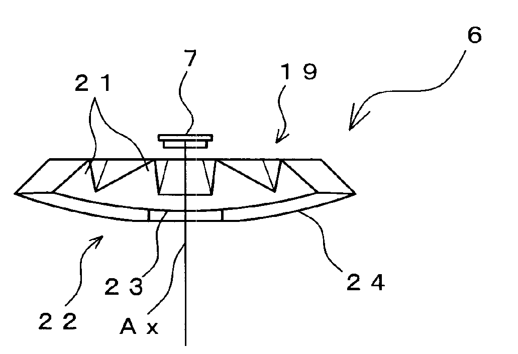
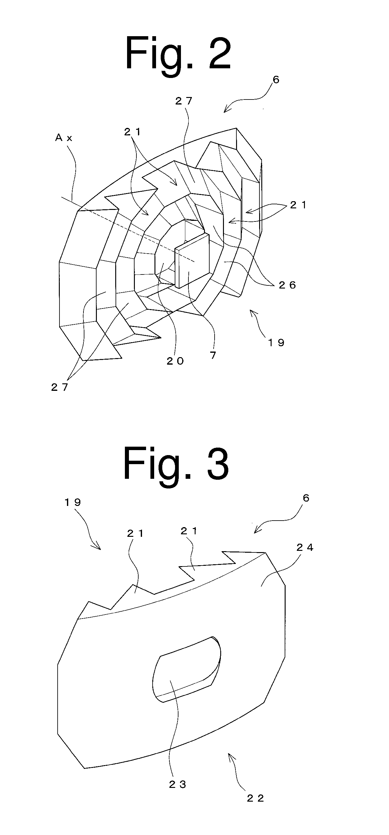
[0035]FIG. 2 is a perspective view illustrating a light incident surface of an optical lens for a vehicle light, and FIG. 3 is a perspective view illustrating a light output surface for the optical lens of FIG. 2. FIGS. 4A to 4D are a top plan view, a front view, a right side view and a rear side view of the optical lens of FIG. 2, respectively. FIG. 5 is a cross sectional view illustrating the optical lens taken along line A-A′ as shown in FIG. 4B. FIG. 6 is a cross sectional view illustrating the optical lens taken along line B-B′ as shown in FIG. 4B. FIG. 7 is a perspective view illust...


PUM


Abstract

An optical lens for use in a vehicle light can be compact and less expensive and has an outer appearance that has a high commercial value and achieves a high light utilization efficiency. The optical lens can include a light incident surface that receives light from a light source and a light output surface to output the light. The light incident surface can include a center light incident surface formed at its center and being convex toward the light source with a plurality of prisms with a polygonal shape formed radially from its center to its periphery. The light output surface can include a toroidal surface corresponding to the center light incident surface and a surrounding light output surface corresponding to the prisms.

Description

[0001]This application claims the priority benefit under 35 U.S.C. §119 of Japanese Patent Application No. 2009-005021 filed on Jan. 13, 2009, which is hereby incorporated in its entirety by reference.TECHNICAL FIELD[0002]The presently disclosed subject matter relates to an optical lens configured to condense light emitted from a light source and distribute the condensed light within a predetermined range. The presently disclosed subject matter also relates to a vehicle light for a day-time-running light, utilizing the same.BACKGROUND ART[0003]A known conventional vehicle light can include a light source, a reflector for reflecting light emitted from the light source, and a light controlling / distributing lens for controlling the light emitted from the light source to distribute the light within a range in accordance with a light distribution specification (see, for example, U.S. Patent Application Publication 2005 / 219865A1 corresponding to Japanese Patent Application Laid-Open No. 2...

Claims


Application Information

Patent Timeline
IPC IPC(8): B60Q1/00F21V5/00F21V7/00
CPCB60Q1/0041B60Q2400/30F21S48/1233G02B3/08F21V5/04F21V7/0091F21V5/02F21S41/28
Inventor FUTAMI, TAKASHI
Owner STANLEY ELECTRIC CO LTD
Why Eureka
Try Eureka