Rotor Cooling Circuit

a cooling circuit and rotating shaft technology, applied in the field of rotating cooling circuits, can solve the problems of low cycle fatigue of rotating components, affecting the overall efficiency of the machine and the final power output, and affecting the performance of the system

Inactive Publication Date: 2010-07-15
GENERAL ELECTRIC CO
View PDF15 Cites 10 Cited by
  • Summary
  • Abstract
  • Description
  • Claims
  • Application Information

AI Technical Summary

Problems solved by technology

As such, the rotor components are subject to low cycle fatigue (LCF), embrittlement and creep issues, which are detrimental to the performance of the system.
This cooling scheme uses an excess amount of CCA, which impacts the overall efficiency of the machine and the final power output.
Additionally, the greater amount of cooling flow requires a larger size heat exchanger, which also results in an efficiency loss in the overall scheme of the system.

Method used


Image

  • Rotor Cooling Circuit
  • Rotor Cooling Circuit

Examples


Embodiment Construction

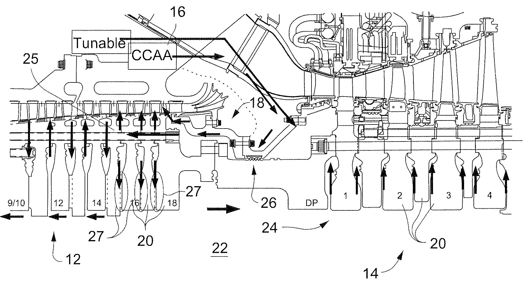
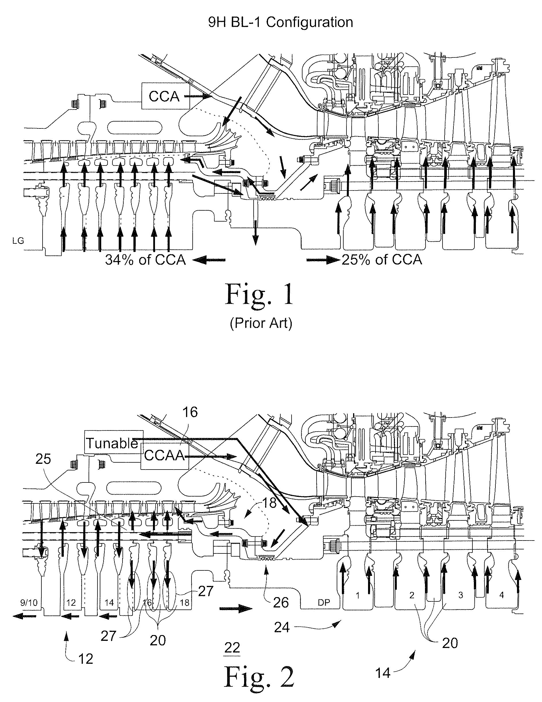
[0011]FIG. 2 is a cross sectional view of a gas turbine including the cooling circuit of the described embodiment. A unit rotor in the gas turbine includes a compressor rotor 12 and a turbine rotor 14. The cooling circuit includes a source of cooled cooling air 16, which is routed through the compressor discharge casing (CDC) via a heat exchanger upstream of the unit rotor.

[0012]The cooling circuit includes a first cooling path 18 defined through openings in rotor wheels 20 of the compressor rotor 12. The first cooling path 18 directs the cooled cooling air across the rotor wheels 20 and into a bore section 22 of the compressor rotor 12.

[0013]A second cooling path 24 is defined in series with the first cooling path 18. The second cooling path 24 directs the cooled cooling air across rotor wheels 20 of the turbine rotor 14.

[0014]A small amount of compressor discharge flow (to be used for rotor cooling) is routed to the rotor through the CDC extraction port to the heat exchanger skid ...


PUM


Abstract

A cooling circuit serves to provide cooling air in a rotor having a compressor rotor and a turbine rotor. The cooling circuit includes a first cooling path through the compressor rotor in series with a second cooling path through the turbine rotor such that one amount of cooling air is used for cooling both the compressor rotor and the turbine rotor. The construction enables a reduction in cooling air requirements, thereby increasing power plant efficiency.

Description

BACKGROUND OF THE INVENTION[0001]The present invention relates to rotor cooling and, more particularly, to a rotor cooling circuit including combined compressor cooling and turbine cooling to thereby increase efficiency and total power output.[0002]In a gas turbine, the unit rotor during its full load operation experiences temperatures higher than the material capability. As such, the rotor components are subject to low cycle fatigue (LCF), embrittlement and creep issues, which are detrimental to the performance of the system. The unit rotor wheels require a positive purge system to cool the wheels during full load operation. The rotor purge also maintains uniform wheel temperatures during startup and shutdown to achieve good wheel to wheel behavior.[0003]Typically, the unit rotor receives cooled cooling air (CCA) through the compressor discharge casing (CDC) and the inner barrel. This flow is channeled from the aft end of the compressor cavity, down through the air-tubes in the dis...

Claims


Application Information

Patent Timeline
Patent Type & Authority Applications(United States)
IPC IPC(8): F01D5/18
CPCF01D5/082F02C7/18F01D5/085
Inventor DESAI, TUSHAR S.WALKER, ROGER CLAYTONGUTTA, RICHARD FRANCISCASANOVA, FERNANDO J.MEENAKSH, RAVI
Owner GENERAL ELECTRIC CO
Why Eureka
Try Eureka