Gear set and nutation gear set

a gear set and gear set technology, applied in the direction of gearings, oblique crank gearings, wobble plate gearings, etc., can solve the problems of noise loss or noise, insufficient to prevent rollers, etc., to prevent the member from lifting or slipping

Active Publication Date: 2010-07-15
OGINO IND +1
View PDF5 Cites 11 Cited by
  • Summary
  • Abstract
  • Description
  • Claims
  • Application Information

AI Technical Summary

Benefits of technology

[0007]The invention provides a gear set and nutation gear set that are able to prevent lifting or slipping of members that constitute teeth.

Problems solved by technology

A situation that the rollers that constitute the convex teeth lift from the grooves of the first gear or slip off from the grooves (tooth jumping) leads to a torque loss or occurrence of noise, so it is undesirable.
JP-A-11-315908 is not intended to actively press the rollers against the grooves of the first gear, so it is insufficient to prevent the rollers from lifting from the grooves of the first gear or slipping off from the grooves.

Method used


Image

  • Gear set and nutation gear set
  • Gear set and nutation gear set
  • Gear set and nutation gear set

Examples


first embodiment

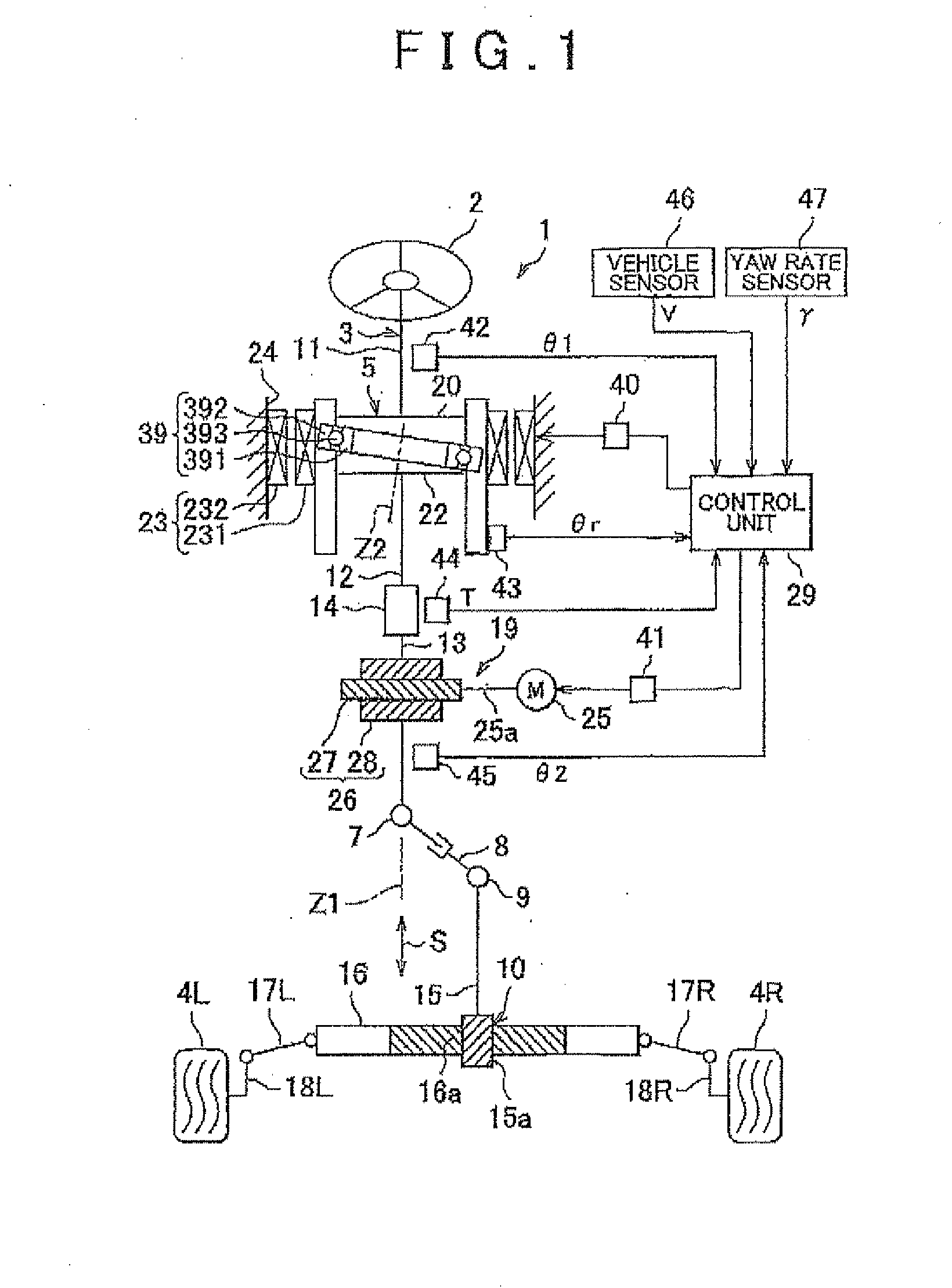
[0022]FIG. 1 is a view that shows the schematic configuration of a vehicle steering system 1 equipped with a transmission ratio variable mechanism according to the invention. Referring to FIG. 1, the vehicle steering system 1 applies steering torque, given to a steering member 2 such as a steering wheel, to respective right and left steered wheels 4R and 4L via a steering shaft 3, or the like. The vehicle steering system 1 has a variable gear ratio (VGR) function. The VGR function is able to change a transmission ratio θ2 / θ1 that is the ratio of a steered angle θ2 of each steered wheel to a steering angle θ1 of the steering member 2.

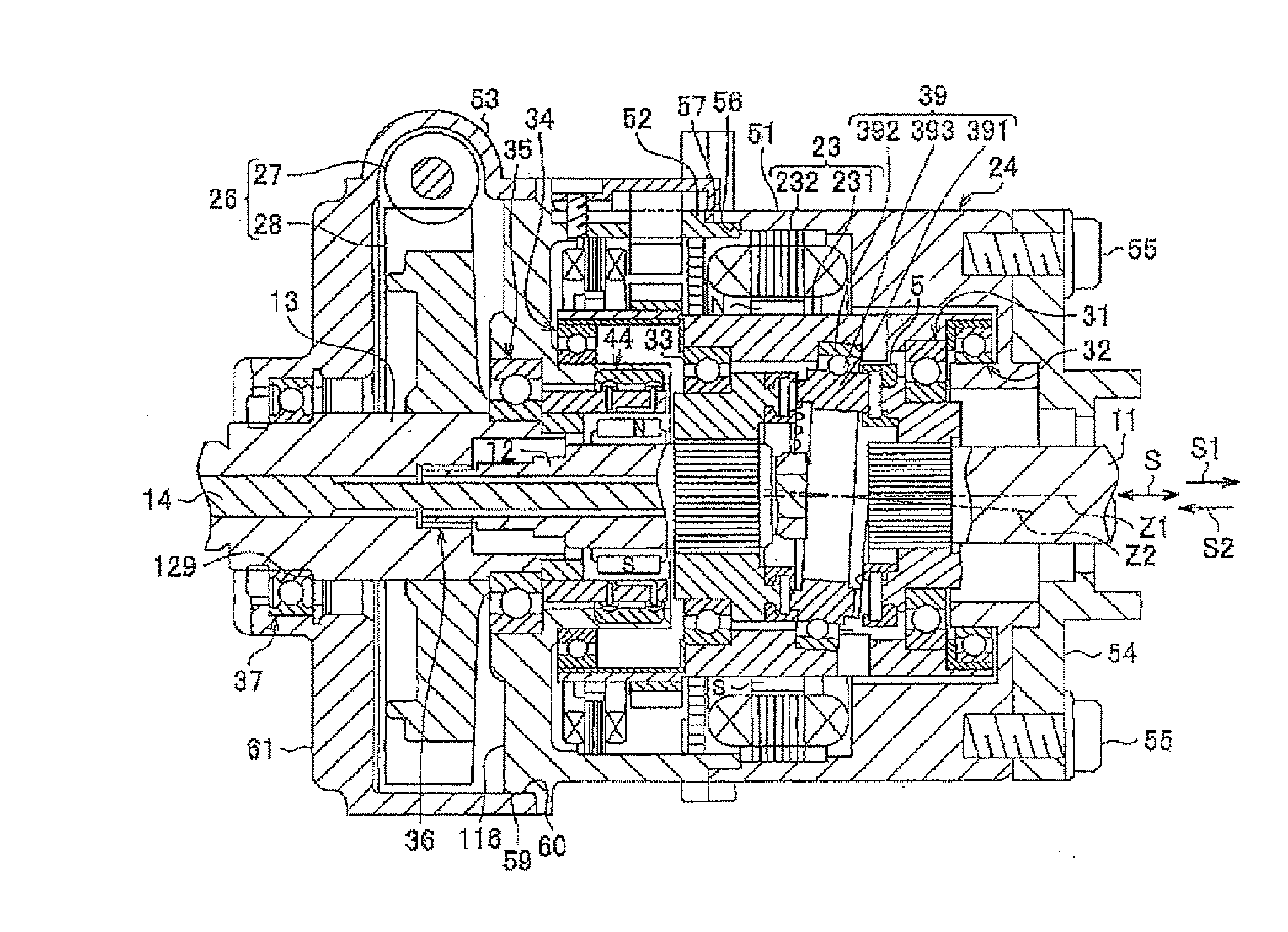
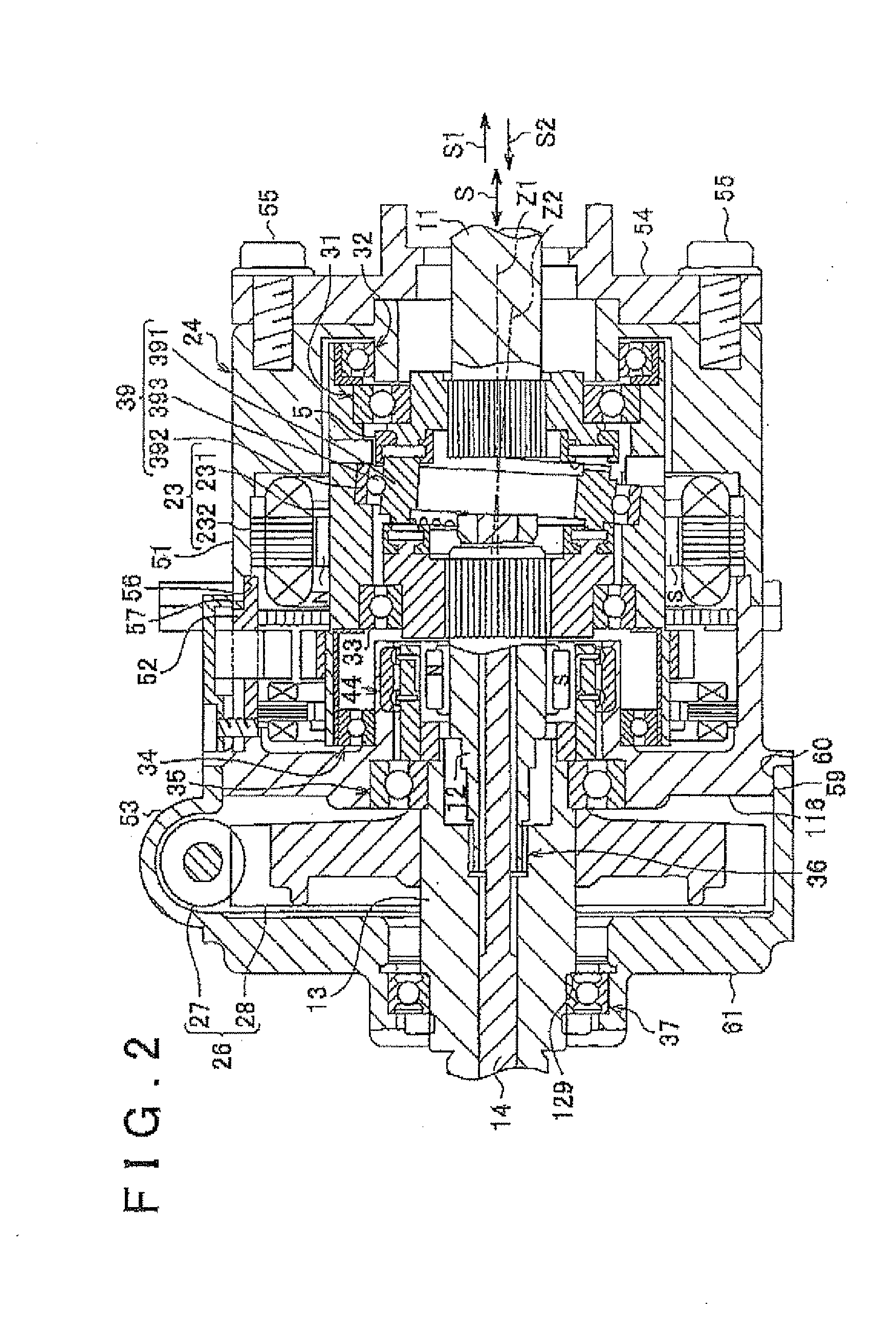
[0023]The vehicle steering system 1 includes the steering member 2 and the steering shaft 3 coupled to the steering member 2. The steering shaft 3 includes first to third shafts 11 to 13 that are arranged along the same axis. The respective central axes of the first to third shafts 11 to 13 are also the rotation axes of the first to third shafts 11 to 13...

second embodiment

[0108]For example, as in the case of a second embodiment shown in FIG. 11, truncated cone-shaped pins 77A and retention grooves 79A and tooth grooves 80A that coincide with the shapes of the pins 77A may be used. Each pin 77A has a diameter that reduces as it goes radially inward of the input member body 201.

[0109]In addition, it is also applicable that, in only one of the first and second gear sets 78 and 88, the first contact angle β is larger than the second contact angle α.

[0110]Furthermore, the above embodiments are applied to a column electric power steering system in which the steering assist motor 25 is arranged in the steering column; however, the aspect of the invention is not limited to this configuration. For example, the aspect of the invention may be applied to a rack assist electric power steering system in which the steering assist motor 25 is provided for a steering rack housing. In addition, the aspect of the invention may be applied to a pinion assist power steeri...


PUM


Abstract

A first gear set includes an input member that serves as a first gear and an inner ring that serves as a second gear. A first end of the inner ring is inclined with respect to the input member and is in mesh with the input member. The input member has a plurality of retention grooves that are formed in an input member body and a plurality of pins that are retained in the respective retention grooves and that respectively constitute teeth of the input member. The first end has a plurality of tooth grooves that are engageable with the pins. A resultant force of forces applied to each pin from the retention groove and the tooth groove urges the pin toward the retention groove.

Description

INCORPORATION BY REFERENCE[0001]The disclosures of Japanese Patent Application No. 2009-004859 filed on Jan. 13, 2009 including the specification, drawings and abstract, is incorporated herein by reference in its entirety.BACKGROUND OF THE INVENTION[0002]1. Field of the Invention[0003]The invention relates to a gear set and a nutation gear set.[0004]2. Description of the Related Art[0005]Some of gear sets include two bevel gears in mesh with each other (for example, see Japanese Patent Application Publication No. 11-315908 (JP-A-11-315908)). In JP-A-11-315908, the first and second gears are in mesh with each other, and the second gear is inclined with respect to the first gear. The first gear has a plurality of grooves, and rollers are arranged in the grooves so as to protrude from the grooves. The rollers form semi-cylindrical convex teeth. On the other hand, the second gear has a plurality of grooves, and has semi-cylindrical concave teeth. Then, as the first gear rotates, part of...

Claims


Application Information

Patent Timeline
Patent Type & Authority Applications(United States)
IPC IPC(8): F16H23/00F16H1/12
CPCB62D5/008F16H1/321Y10T74/1966F16H55/10F16H35/008
Inventor KUROUMARU, YOSHIKAZUNITANO, MASAHIDEMOTOYAMA, SATOSHI
Owner OGINO IND
Why Eureka
Try Eureka