
Wiper blade

a technology of a wedge and a blade, applied in the field of wedges, can solve the problems of causing the wiping wedge in the region of the tilting web causing the noise of flipping over, and causing the wedge to turn over very quickly

Active Publication Date: 2010-07-22
ROBERT BOSCH GMBH
View PDF16 Cites 5 Cited by
  • Summary
  • Abstract
  • Description
  • Claims
  • Application Information

AI Technical Summary

Benefits of technology

[0002]The wiper blade has the advantage of a defined geometry with which the wiper lip rests on the window during use. Said geometry which, in the case of wiper blades having a “tilting web”, is achieved by tightening the flipped over wiper blade wedge, on the lower side of which the wiper lip is integrally formed, has proven important for a homogeneous wiping operation. In particular rattling and squeaking noises are avoided and a neat wiping pattern is achieved therewith. On the other hand, the construction of the tilting web has proven disadvantageous in the turning-over behavior in the reversal positions of the wiping movement. The laterally very stiff design of the spring rails of “joint-free” wiper blades causes the wiping wedge in the region of the tilting web to turn over very rapidly and, as a result, to produce an annoying flipping-over noise.
[0004]The quality of the wiping pattern can be kept good even under extreme conditions if the point angle is between 75 degrees and 135 degrees because the dragging position is therefore conformed with even better. An optimum result is achieved with a point angle of 90° because then the average angle between the window surface and the side wall of the wiper lip corresponds to 45 degrees which has proven the best value in practice.
[0005]If the radius is kept smaller than 75 micrometers, the contact surface is reduced, as a result of which, at the same application of force via the wiper arm, the pressure between the contact surface and window surface and therefore the tightness are increased, which increases the quality of the wiping pattern. If the radius is selected to be smaller than 50 micrometers, the force applied by the wiper arm can be reduced and the entire system relieved of load.
[0006]In conventional wiper blade materials, the stated geometrical values result in an optimized wiping quality which can be further improved if the wiper strip material does not exceed a modulus of elasticity of 10 Newtons per square millimeter. As a result, the deformation of the contact surface is kept within justifiable limits. If the modulus of elasticity is managed to be kept smaller than or equal to 5 Newtons per square millimeter, then, in conjunction with the claimed geometrical values, the wiper lip point is deformed on the window in an optimum manner for the wiping operation and the tightness at the contact surface.
[0007]A considerably larger radius can be selected if at least the wiper lip is coated with a layer, the thickness of which does not exceed 100 micrometers. Radii of up to 10 millimeters are therefore possible. The latter can be produced in a particularly simple manner, for example by extrusion, and do not have to be cut.

Problems solved by technology

On the other hand, the construction of the tilting web has proven disadvantageous in the turning-over behavior in the reversal positions of the wiping movement.
The laterally very stiff design of the spring rails of “joint-free” wiper blades causes the wiping wedge in the region of the tilting web to turn over very rapidly and, as a result, to produce an annoying flipping-over noise.

Method used


Image

  • Wiper blade
  • Wiper blade
  • Wiper blade

Examples


Embodiment Construction

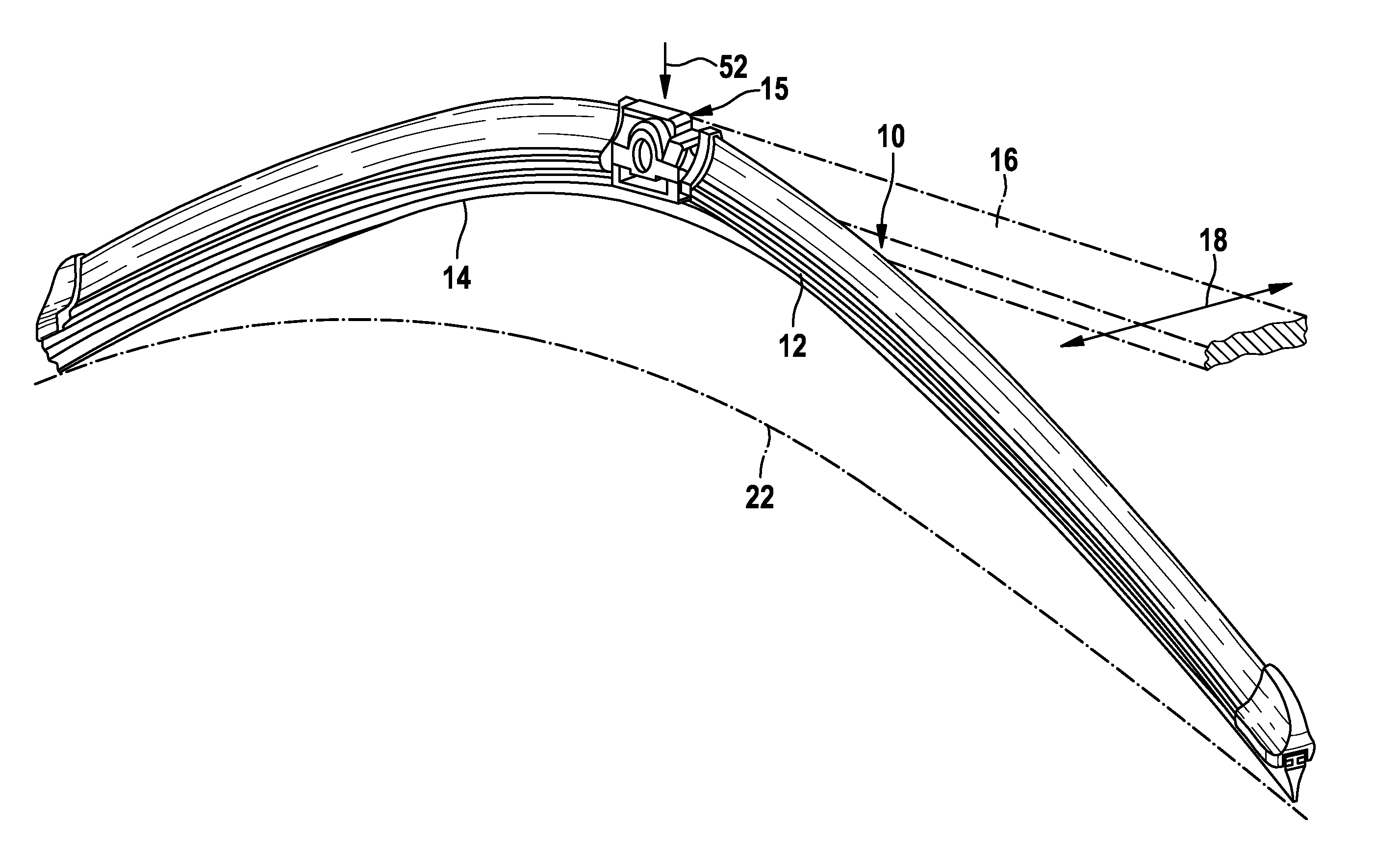
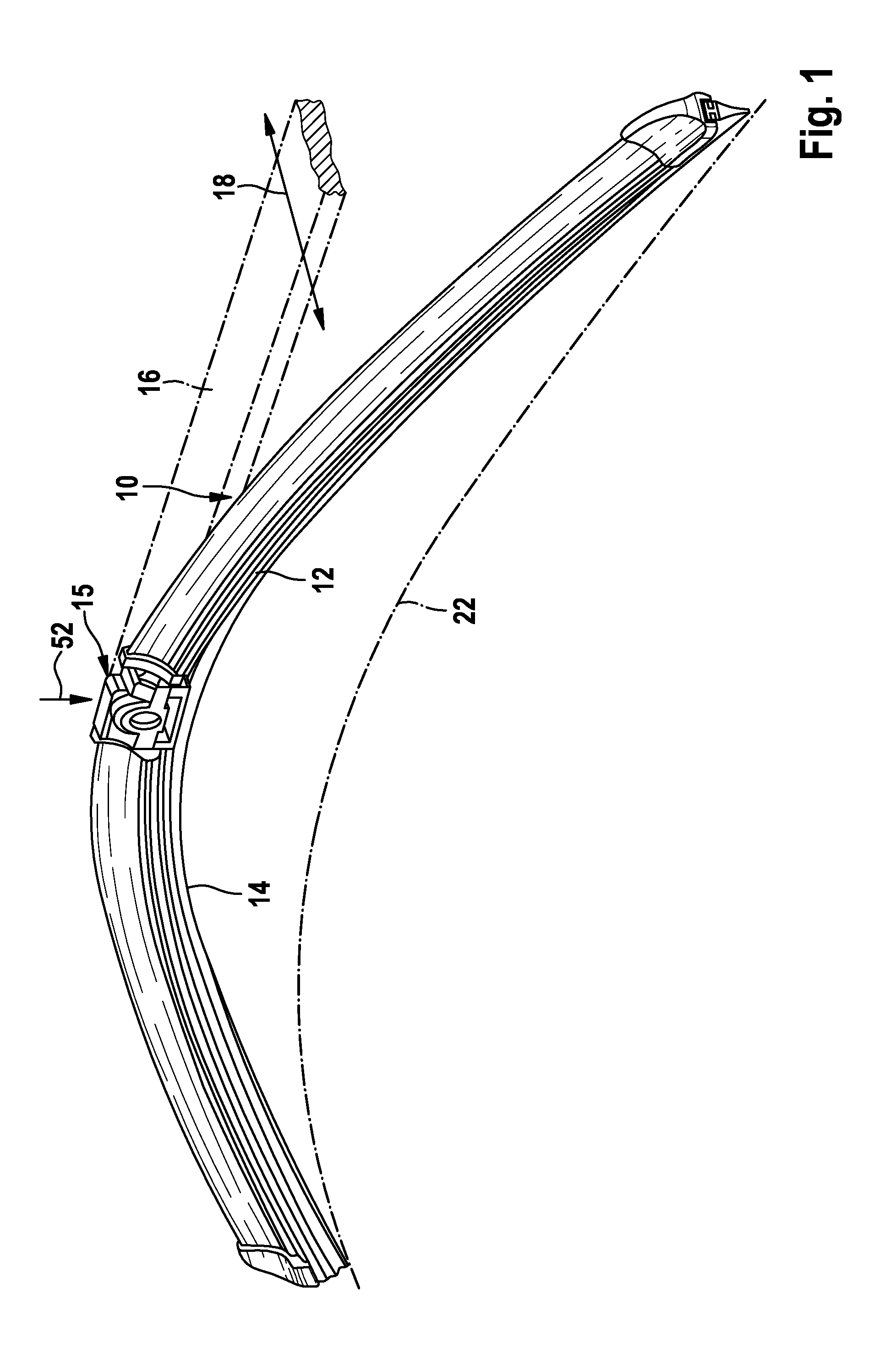
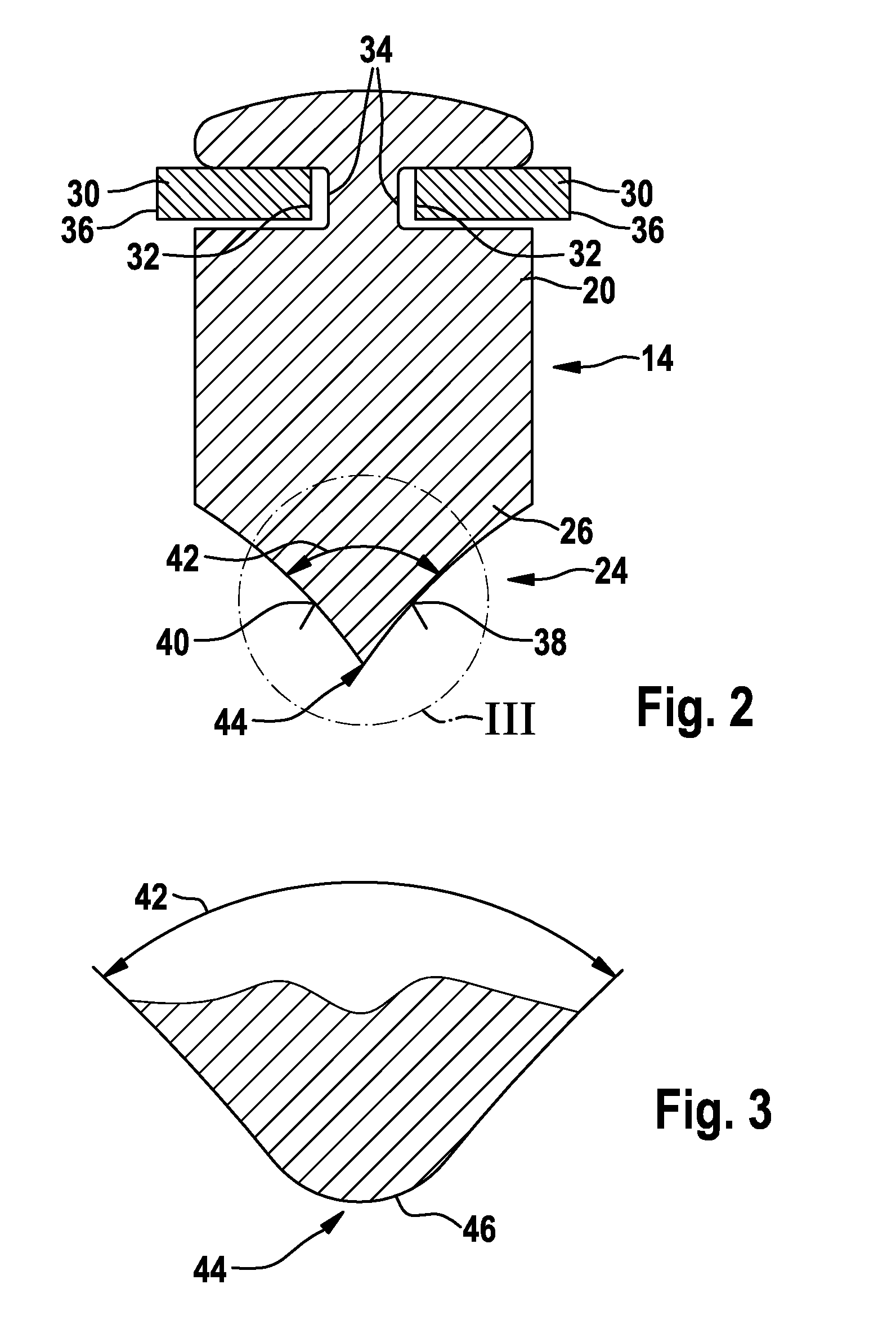
[0018]A wiper blade 10 has a spring-elastic supporting element 12 which is elongated in the manner of a band and is in the form of two spring rails 30 running parallel at a distance from each other. Said spring rails are inserted by their mutually facing, inner edge strips 32 in longitudinal grooves 34 in a head strip 20 of a wiper strip 14 while their outer edge strips 36 protrude laterally for a distance out of the longitudinal grooves 34. Toward a vehicle window 22, a wiper strip head 20 is adjoined by a wiper lip 26 which slides over the vehicle window 22 in the direction of a double arrow 18 during a wiping movement. For this purpose, a wiper arm 16 drives the wiper blade 10 via a connection device, the wiper-blade-side part 15 of which can be connected to the wiper arm 16 in an articulated and releasable manner while said part sits fixedly in the central region of the wiper blade 10 on the supporting element 12 thereof. At the same time, the wiper arm 16 loads the wiper blade ...


PUM

PropertyMeasurementUnit
Lengthaaaaaaaaaa
Lengthaaaaaaaaaa
Thicknessaaaaaaaaaa

Abstract

The invention relates to a wiper blade (10) with a wiper strip (14) made of elastic material and having a wiper strip head (20) and a wiper lip (26) which can be placed on a window (22) to be wiped, wherein the wiper lip (26) is designed as a wedge-shaped extension (24) of the wiper strip head (20) and has a point angle (42) of between 60 degrees and 150 degrees, said point angle leading into a contact surface (44) having a radius (46) of smaller than 100 micrometers, and also to a method for the production of said wiper blade.

Description

BACKGROUND OF THE INVENTION[0001]The invention is based on a wiper. DE 2336271 A1 has already disclosed a wiper blade with a wiper bracket which is composed of flexible plastic and is preshaped in a manner corresponding to the curvature of a windshield. The wiper blade is fastened in a groove of the wiper bracket or is produced integrally with the wiper bracket. The wiping quality of said wiper blade does not always meet expectations.SUMMARY OF THE INVENTION[0002]The wiper blade has the advantage of a defined geometry with which the wiper lip rests on the window during use. Said geometry which, in the case of wiper blades having a “tilting web”, is achieved by tightening the flipped over wiper blade wedge, on the lower side of which the wiper lip is integrally formed, has proven important for a homogeneous wiping operation. In particular rattling and squeaking noises are avoided and a neat wiping pattern is achieved therewith. On the other hand, the construction of the tilting web h...

Claims


Application Information

Patent Timeline
IPC IPC(8): B60S1/38B29C37/02
CPCB29C47/00B29C47/0016B29C47/003B60S1/38Y10T29/49789B60S2001/3829B60S2001/3836B60S2001/3898B60S1/3848B29C48/00B29C48/06B29C48/12
Inventor VAN DE ROSTYNE, KRISWYNEN, PAUL
Owner ROBERT BOSCH GMBH
Learn More