Pneumatic tire

a pneumatic tire and tire temperature technology, applied in the field of pneumatic tires, can solve the problems of increasing the temperature of the pneumatic tire, degrading the general driving performance, increasing the tire weight, etc., and achieves the effect of reducing the heat accumulation of the protruding 17 and extending the service li

Active Publication Date: 2010-07-22
BRIDGESTONE CORP
View PDF19 Cites 36 Cited by
  • Summary
  • Abstract
  • Description
  • Claims
  • Application Information

AI Technical Summary

Benefits of technology

[0135]First, when the pneumatic tire 1 having the protrusions 17 obtained based on the above relational expressions rotates, fluid (hereinafter called the main flow S1) flows, as FIG. 6 shows, near the tire surface 15 in a direction opposite to the tire rotation direction in a relative manner. The main flow S1 then collides with the protrusions 17.
[0136]Then, as parts (a) and (b) of FIG. 7 show, the main flow S1 having collided with a front wall face 17a of the protrusion 17 becomes turbulence by separately flowing as a top main flow s1 flowing above a top wall face 17b and as paired side main flows s2 flowing along left and right side wall faces 17c, respectively.
[0137]The turbulence can be generated because the sharp edge part E is formed at a portion connecting the front wall face 17a and the protrusion face 17E and at a portion connecting the side wall faces 17c and the protrusion face 17E. Here, the “sharp” edge does not necessarily have to be sharply pointed, and may be somewhat rounded due to manufacturing processes.
[0138]Since the main flow S1 flowing above the tire surface 15 becomes the turbulence in

Problems solved by technology

Generally, an increase in a tire temperature of a pneumatic tire is considered to be undesirable in terms of durability because such temperature increase promotes a time-dependent change, which is a change in the physical properties of a material, or contributes to damages in a tread part and the like in high-speed driving.
However, the conventional pneumatic tire described above has a problem of degrading general driving performance, such as handling stability

Method used


Image

  • Pneumatic tire
  • Pneumatic tire
  • Pneumatic tire

Examples


first embodiment

Configuration of Pneumatic Tire

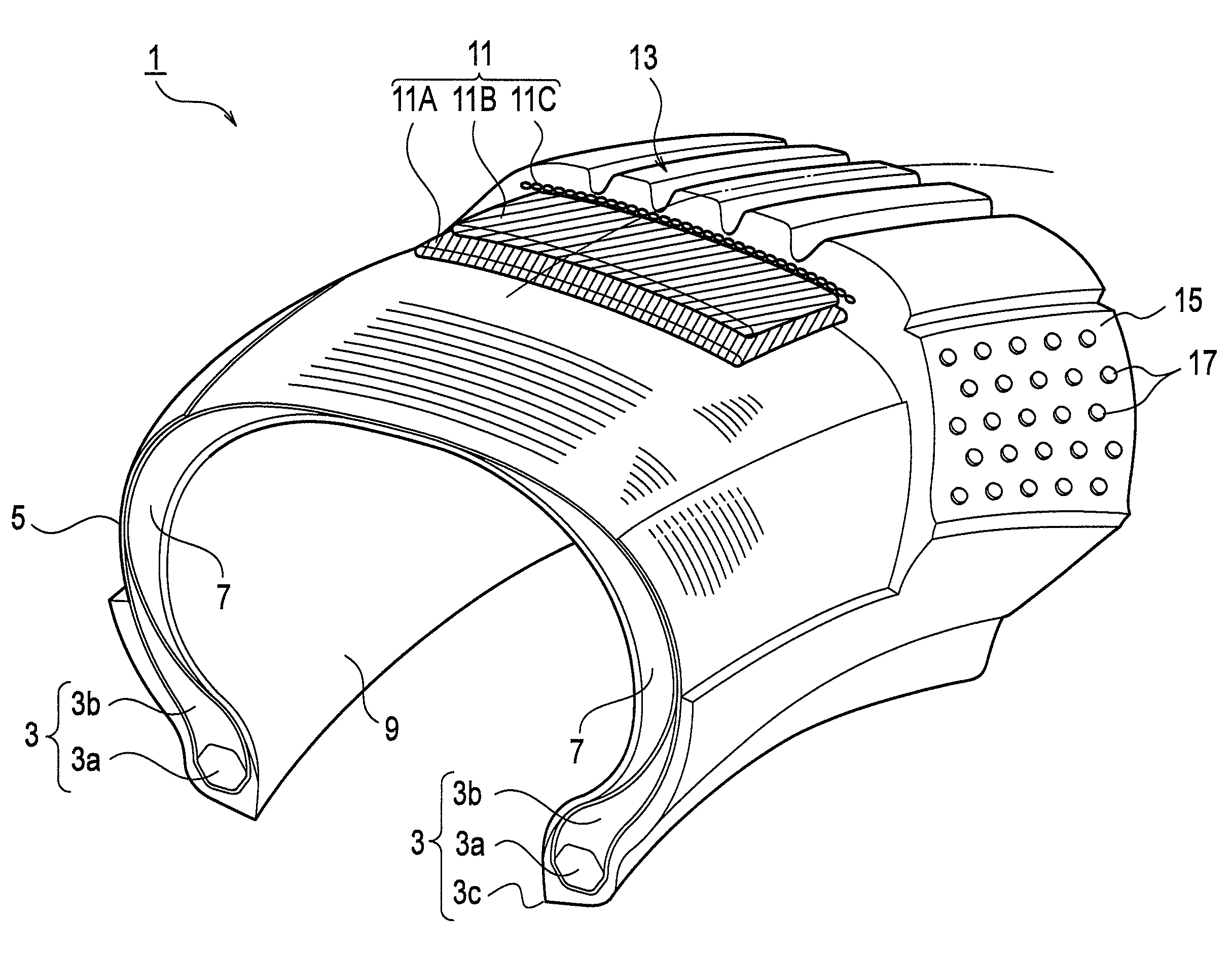
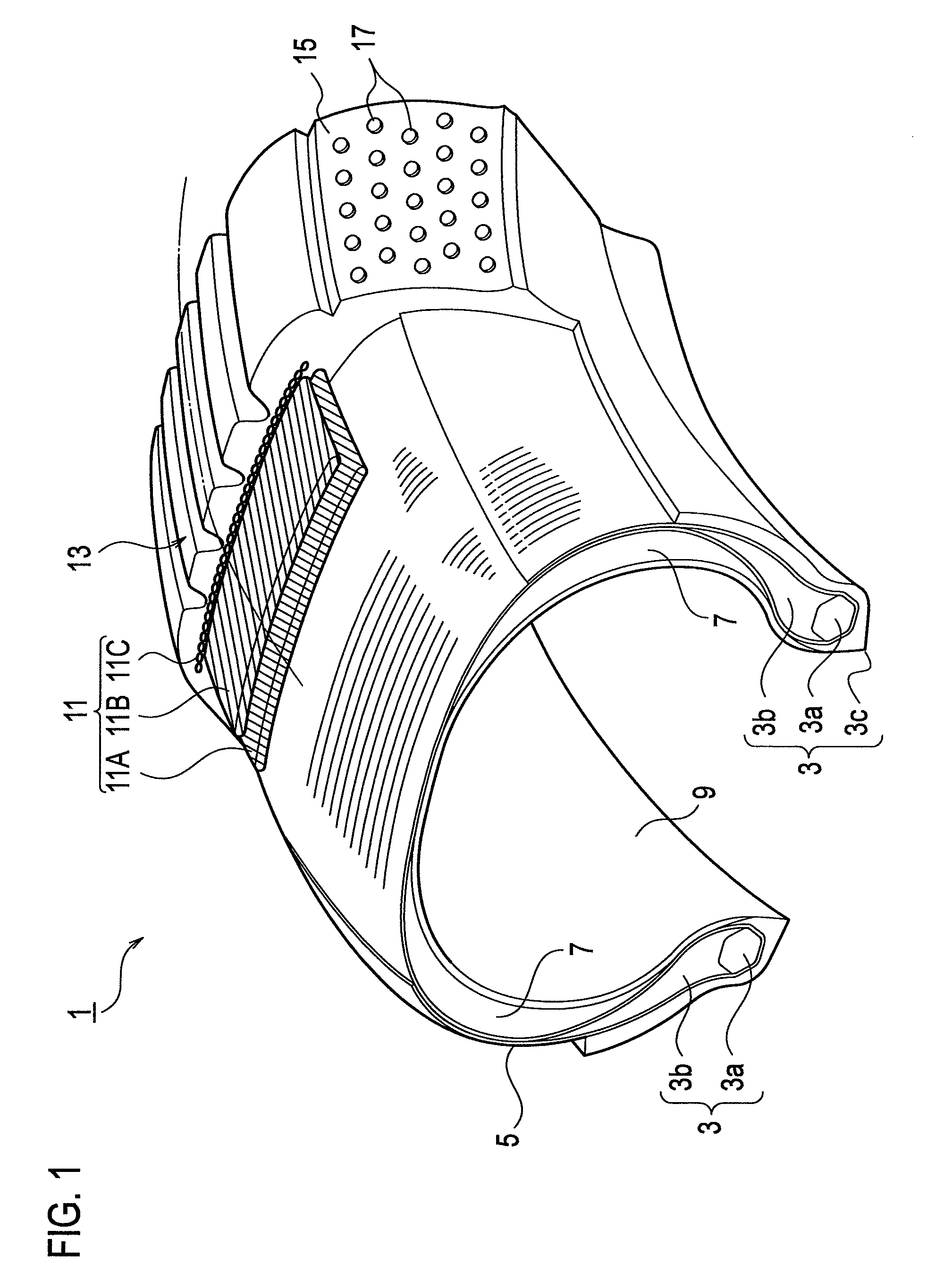
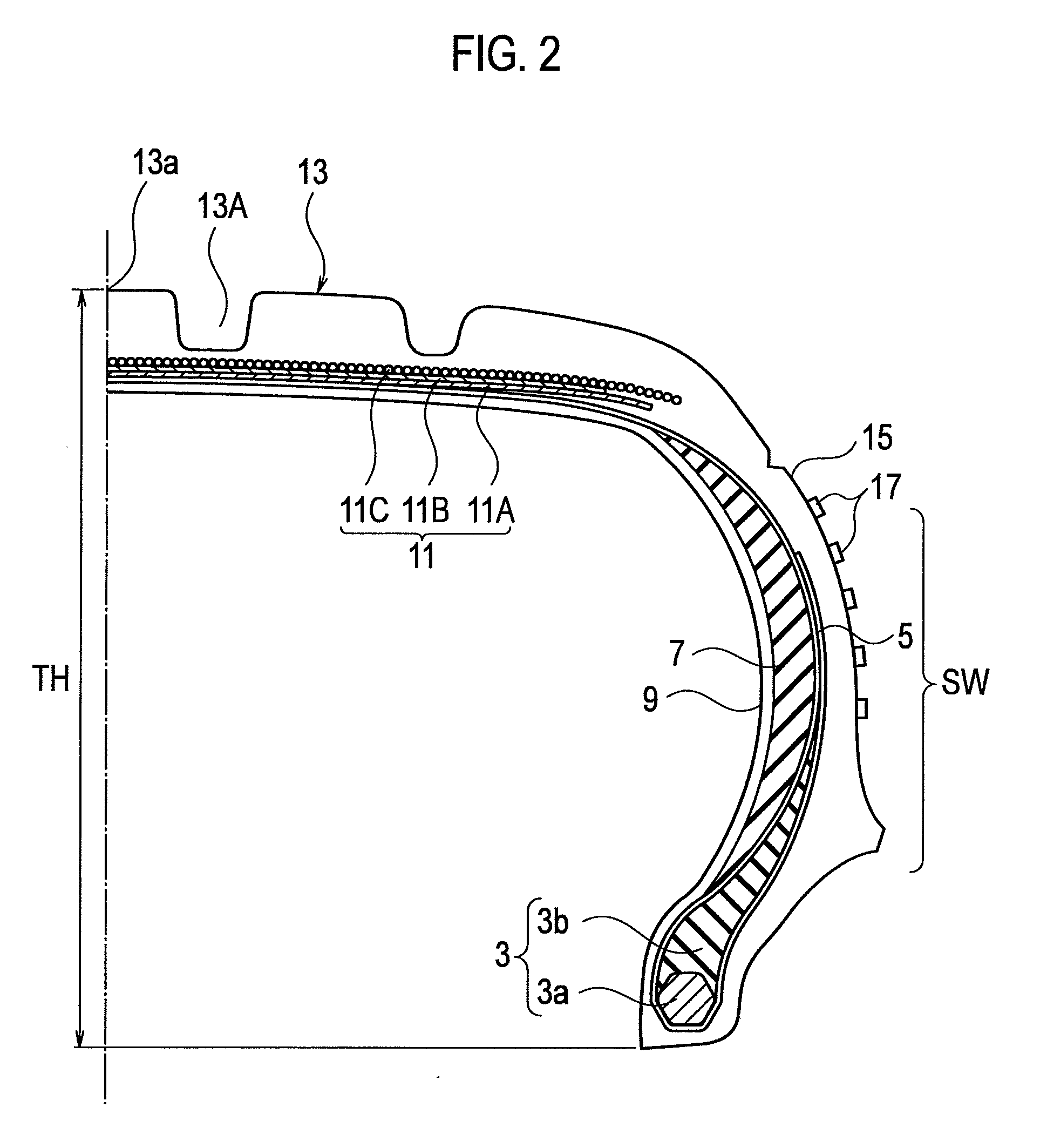
[0103]First, with reference to FIGS. 1 and 2, a description will be given of the configuration of a pneumatic tire according to a first embodiment. FIG. 1 is a partially-exploded perspective view of the pneumatic tire according to the first embodiment. FIG. 2 is a cross-sectional view of the pneumatic tire according to the first embodiment, taken in a tread width direction. Note that the pneumatic tire in this embodiment is a passenger-car radial tire (PCR).

[0104]As FIGS. 1 and 2 show, a pneumatic tire 1 has a pair of bead parts 3. Each of the bead parts 3 includes at least a bead core 3a, a bead filler 3b, and a bead toe 3c. The pneumatic tire 1 also has a carcass layer 5 in a toroid shape. Specifically, the carcass layer 5 bends around each of the bead cores 3a from the inner side in the tread width direction to the outer side in the tread width direction, and then extends by each of sidewall parts SW.

[0105]Sidewall reinforcing layers 7 are formed in...

examples according to first embodiment

Experiments on Arrangement Density of Protrusions

[0152]The protrusions are each made of rubber and mainly shaped as a cylinder or a square pole. The protrusions prepared had the protrusion radial-direction length (L) of various sizes in the range of 0.3 mm to 15 mm. The following experimental method was employed. Specifically, the aforementioned protrusions were arranged on a flat heater emitting a constant amount of heat, and the surface thereof was supplied with air by a blower. A heat transfer coefficient was calculated from the surface temperature and the atmospheric temperature acquired at this time. In this way, the characteristics chart shown in FIG. 12 was obtained with the heat transfer coefficient of a flat plate having no protrusions being evaluated as 100.

[0153]The inventors have discovered that the heat transfer coefficient improves dramatically when the average arrangement density (ρ) of the protrusions 17 satisfies the relationship 1 / {50H(L+10H)}≦ρ≦1 / {H(L+H / 3)}. Speci...

second embodiment

[0177]Next, the configuration of a protrusion 17 according to a second embodiment will be described with reference to FIGS. 19 and 20. Note that the same parts as those of the pneumatic tire 1 according to the above-described first embodiment bear the same reference symbols, and different parts will mainly be described. Namely, points such as the configuration of the pneumatic tire 1 and the arrangement and arrangement density of the protrusions 17 are not repeatedly described. However, some points may be partly repeated.

[0178]FIG. 19 is a perspective view showing a protrusion according to the second embodiment. Part (a) of FIG. 20 is a top view showing the protrusion according to the second embodiment (a view seen in the arrow A of FIG. 19). Part (b) of FIG. 20 is a cross-sectional view showing the protrusion according to the second embodiment seen in the tire radial direction (a B-B cross-sectional view of FIG. 19). Part (c) of FIG. 20 is a front view showing the protrusion accord...


PUM


Abstract

A pneumatic tire 1 according to the present invention has turbulence generating protrusions on a tire surface, each of the turbulence generating protrusions having a sharp edge part. In the pneumatic tire, the following relationships are satisfied: 0.015≦H/√R≦0.64; 1.0≦p/H≦50.0; 0.1≦H/e≦3.0; 1.0≦L/H≦50.0; and 1.0≦(p−w)/w≦100.0, where “R” is a tire radius, “H” is a protrusion maximum height, “p” is a protrusion circumferential-direction interval, “e” is a protrusion radial-direction interval, “L” is a protrusion radial-direction length, and “w” is a protrusion circumferential-direction length.

Description

TECHNICAL FIELD[0001]The present invention relates to a pneumatic tire, and particularly to a pneumatic tire including turbulence generating protrusions generating turbulence.BACKGROUND ART[0002]Generally, an increase in a tire temperature of a pneumatic tire is considered to be undesirable in terms of durability because such temperature increase promotes a time-dependent change, which is a change in the physical properties of a material, or contributes to damages in a tread part and the like in high-speed driving. A reduction in the tire temperature for durability improvement is now an important task to be accomplished especially for tires used under heavy load, including off-the-road radial tires (ORR), truck-and-bus radial tires (TBR), and run-flat tires being driven while punctured (driven under an internal pressure of 0 kPa).[0003]For example, when a run-flat tire having crescent-shaped sidewall reinforcing layers is driven while punctured, deformation in the tire radial direct...

Claims


Application Information

Patent Timeline
IPC IPC(8): B60C23/19B60C13/00
CPCB60C11/01B60C11/042B60C13/02B60C17/0045B60C2011/1338B60C17/0009B60C2011/1361B60C2013/026B60C11/04B60C11/13B60C13/00
Inventor YAMAGUCHI, MASASHI
Owner BRIDGESTONE CORP
Why Eureka
Try Eureka