End boss and composite pressure vessel

a pressure vessel and composite technology, applied in vessel construction details, gas/liquid distribution and storage, closures, etc., can solve the problems of significant challenge in design and connection of end bosses, significant thermal expansion of end bosses, and prolonged use problems, and achieve high elongation

Active Publication Date: 2010-07-22
HEXAGON TECHNOLOGY AS
View PDF3 Cites 14 Cited by
  • Summary
  • Abstract
  • Description
  • Claims
  • Application Information

AI Technical Summary

Benefits of technology

[0015]The metal boss has advantageously a pretension device having adjustable pretension; the pretension can most advantageously be adjusted from outside of the vessel. The pretension device comprises advantageously an outer wedge shaped metal ring arranged with the wedge facing the lid, and an inner oppositely directed wedge shaped polymer ring arranged between the outer metal ring and the inner liner; as the outer metal ring is secured to bolts carried through the lid so that the pretension may be adjusted by tightening the bolts; whereby the outer metal ring is brought closer to the lid and presses the polymer ring against the inner liner. In an advantageous execution the pretension device comprises a polymer ring, which is higher than the groove so that when the lid is tightly fastened, the polymer ring is pressed against the inner liner. The polymer ring may be chosen from many polymers and elastomers and is in an advantageous execution, of the same material as the inner liner, for example HDPE, which is particularly advantageous for inner liner with a high elongation at rupture, meaning over 20% elongation at rupture.

Problems solved by technology

For vessels with a broader use as mentioned above, the design and connecting of the end boss provide a significant challenge.
The metal end boss has a significantly lower thermal expansion than polymer and composite materials, resulting in problems at prolonged use with large temperature and pressure variations.
At high temperature the inner plastic liner will expand more than the metal end boss, resulting in tension bui

Method used


Image

  • End boss and composite pressure vessel
  • End boss and composite pressure vessel
  • End boss and composite pressure vessel

Examples


Embodiment Construction

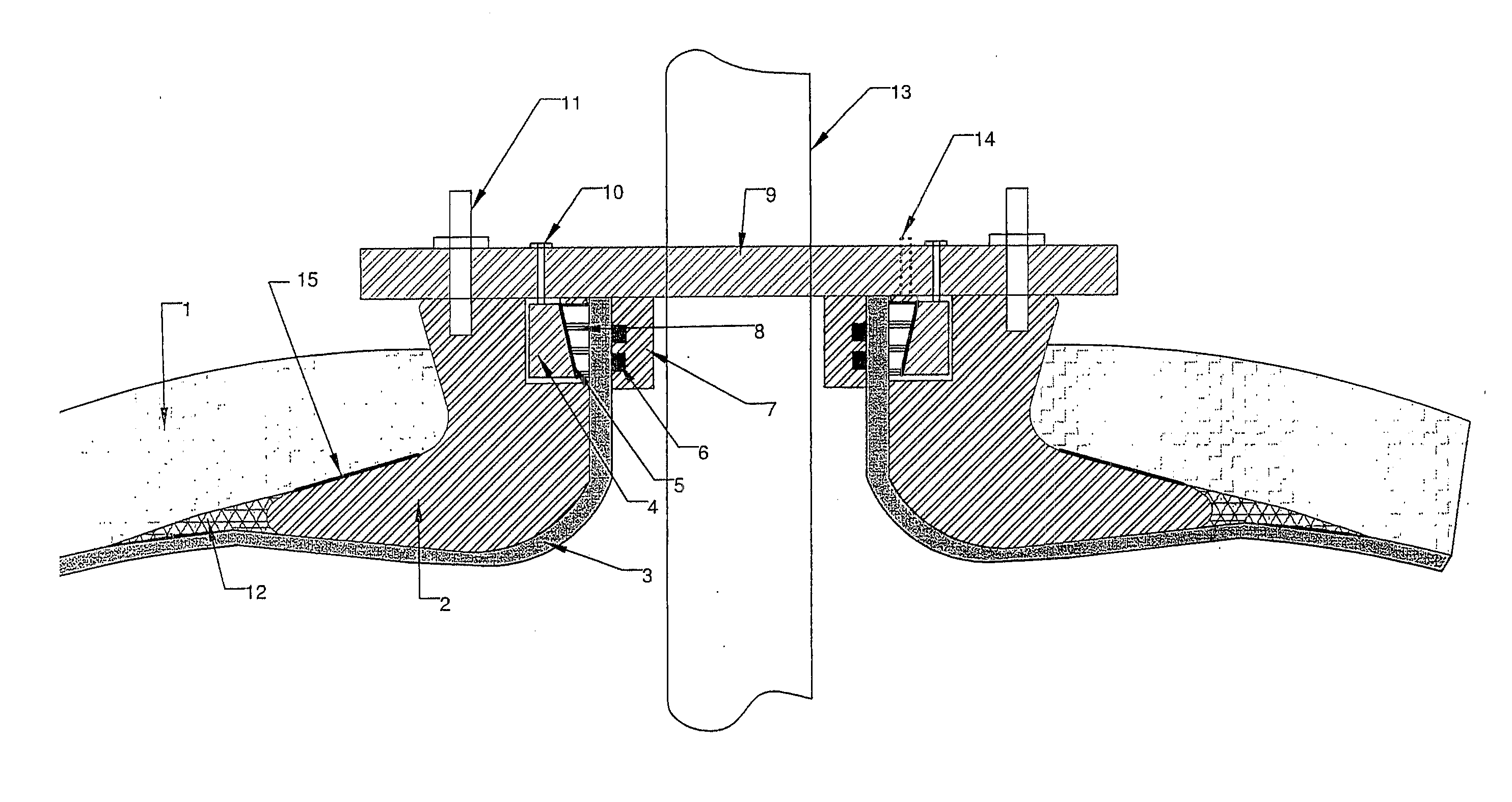
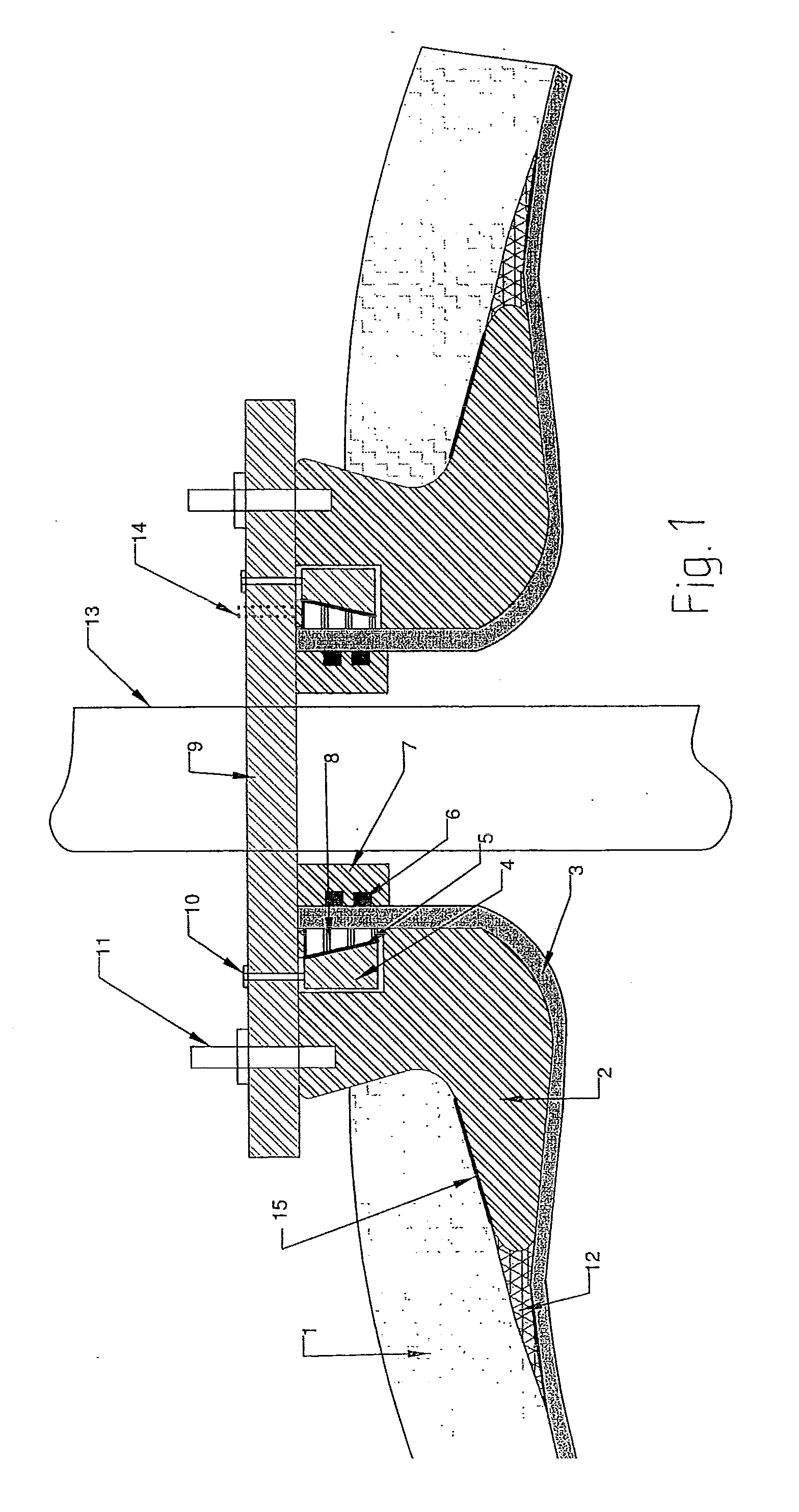
[0023]With reference to FIG. 1, illustrated is a metal end boss 2,9 (metal boss) arranged in an opening in a composite pressure vessel comprising an inner fluid tight liner 3 and an outer fibre reinforced polymer layer 1. The metal boss comprises a short pipe section 2 and a lid 9, in that the lid is arranged on the upper end of the pipe section 2, which extends out of the vessel. The pipe section 2 is arranged through the opening in the vessel and extends to a lower end where an outwardly extending flange on the pipe section is arranged between the outer fibre reinforced polymer layer 1 and the inner liner 3 in the vessel so that the pipe section remains fastened to the vessel. The inner liner 3 extends upwards through the opening of the pipe section to the said lid. Inside of the inner liner, at a distance nearest the lid, is arranged a sealing surface 7 in the form of a metal surface 7 interfacing the inner liner. In a groove on the metal surface 7, two gas tight seals 6 are arra...


PUM

PropertyMeasurementUnit
Tensionaaaaaaaaaa

Abstract

End boss (2,9) arranged in an opening of a composite pressure vessel comprising an inner fluid tight liner (3) and an outer reinforced polymer layer (1), which end boss comprises a short pipe section (2) and a lid (9), the lid is arranged at an upper end of the pipe section (2) that extends outwards from the vessel, the pipe section (2) is arranged through the opening of the vessel and extends to a lower end where an outwardly extending flange on the pipe section is arranged between the outer reinforced polymer layer (1) and the inner liner (3) in the vessel,
distinguished in that
    • the inner liner (3) extends upwards through the opening of the pipe section to said lid,
    • on the inside of the inner liner, in a distance nearest to the lid, a sealing surface is arranged, the sealing surface lies against the inner liner and has at least one gas tight seal interfacing against the inner liner as the sealing surface is integrated with the lid or is a sleeve or a pipe section which is sealingly fastened to the lid, and
    • on the outside of the inner liner, in a groove nearest to the lid and pipe section, around the upper end of the pipe section, a pre-tensioning device is arranged (4, 8, 10, 16), which regardless of the pressure in the vessel presses the inner liner (3) against said sealing surface and the at least one gas tight seal (6).
Composite pressure vessel with such end boss.

Description

FIELD OF THE INVENTION[0001]The current invention relates to composite pressure vessels for the storing of compressed natural gas and other fluids. More precisely, the invention relates to an end boss, which is a termination end for use in vessels of to said type and a composite pressure vessel equipped with such end boss.BACKGROUND OF THE INVENTION AND PRIOR ART[0002]In recent years the use of composite pressure vessel to manage hydrocarbons under high pressure has become more current. Such vessels should preferably be usable for a broad spectre of hydrocarbons, from dry, compressed natural gas, so-called CNG, to unprocessed well fluids from oil production. Well fluids would typically be an oil based liquid under pressure, containing compressed gas as well as pollution in the form of water, sand, H2S, CO2, etc. In order to make optimal use of the storing facility for the pressure vessel, dry gas is stored at low temperatures since this increases the compressibility of the gas, whil...

Claims


Application Information

Patent Timeline
IPC IPC(8): F17C1/02B65D45/32B65D45/00
CPCF17C13/06F17C2223/036F17C2201/056F17C2203/0604F17C2203/0619F17C2203/066F17C2203/0663F17C2209/2109F17C2209/228F17C2209/234F17C2221/013F17C2221/033F17C2221/037F17C2223/0123F17C2223/035F17C2205/0305
Inventor JENKINS, PETERLOTVEIT, SVEIN AREAXELSSON, GUNNAR
Owner HEXAGON TECHNOLOGY AS
Why Eureka
Try Eureka