

Illumination system comprising a compound with low thermal expansion coefficient
a technology of thermal expansion coefficient and compound, applied in the direction of basic electric elements, light sources, electrical appliances, etc., can solve the problem of reliability of phosphor converted leds, and achieve the effect of high reliability of phosphor
Inactive Publication Date: 2010-07-22
KONINKLIJKE PHILIPS ELECTRONICS NV
View PDF10 Cites 13 Cited by
- Summary
- Abstract
- Description
- Claims
- Application Information
AI Technical Summary
Benefits of technology
[0006]It is an object of the present invention to provide an illumination system which is at least partly able to overcome the above-mentioned drawbacks and is especially usable within a wide range of applications and especially allows the fabrication and / or setup of highly reliable phosphor converted LEDs.
Problems solved by technology
Especially the reliability of phosphor converted LEDs is an important issue in the industrialization of these illumination systems.
Method used
View moreImage
Smart ImageViewing Examples

Examples
example i
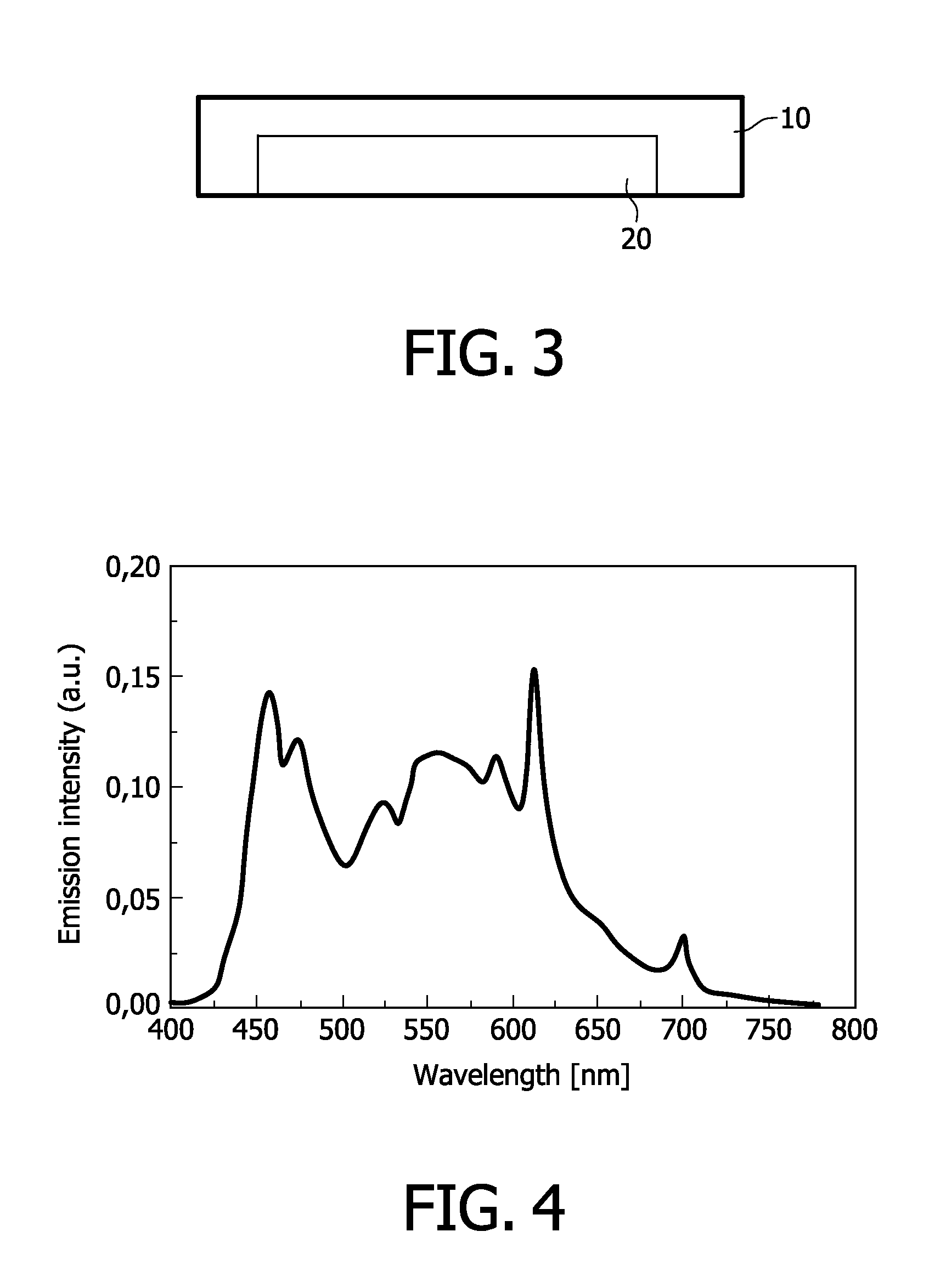
[0126]In this example, a LED was made comprising a die, that is surrounded by a ceramic composite material with a thermal expansion coefficient close to zero. The composite is composed out of a Cerium doped garnet, i.e. (Y,Gd,Lu)3Al5012:Ce,Pr and out of a Europium doped tungstate or molybdate, i.e. LiLaW2O8:Eu. The spectrum of the LED is shown in FIG. 4.
Login to View More PUM
| Property | Measurement | Unit |
|---|---|---|
| band gap | aaaaa | aaaaa |
| Debye-Temperature | aaaaa | aaaaa |
| Debye-Temperature | aaaaa | aaaaa |
Abstract
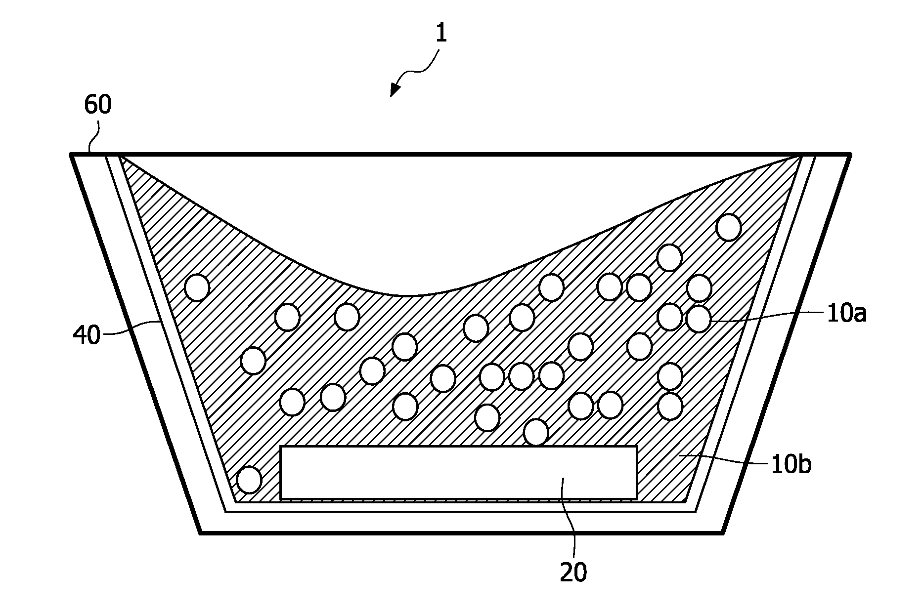
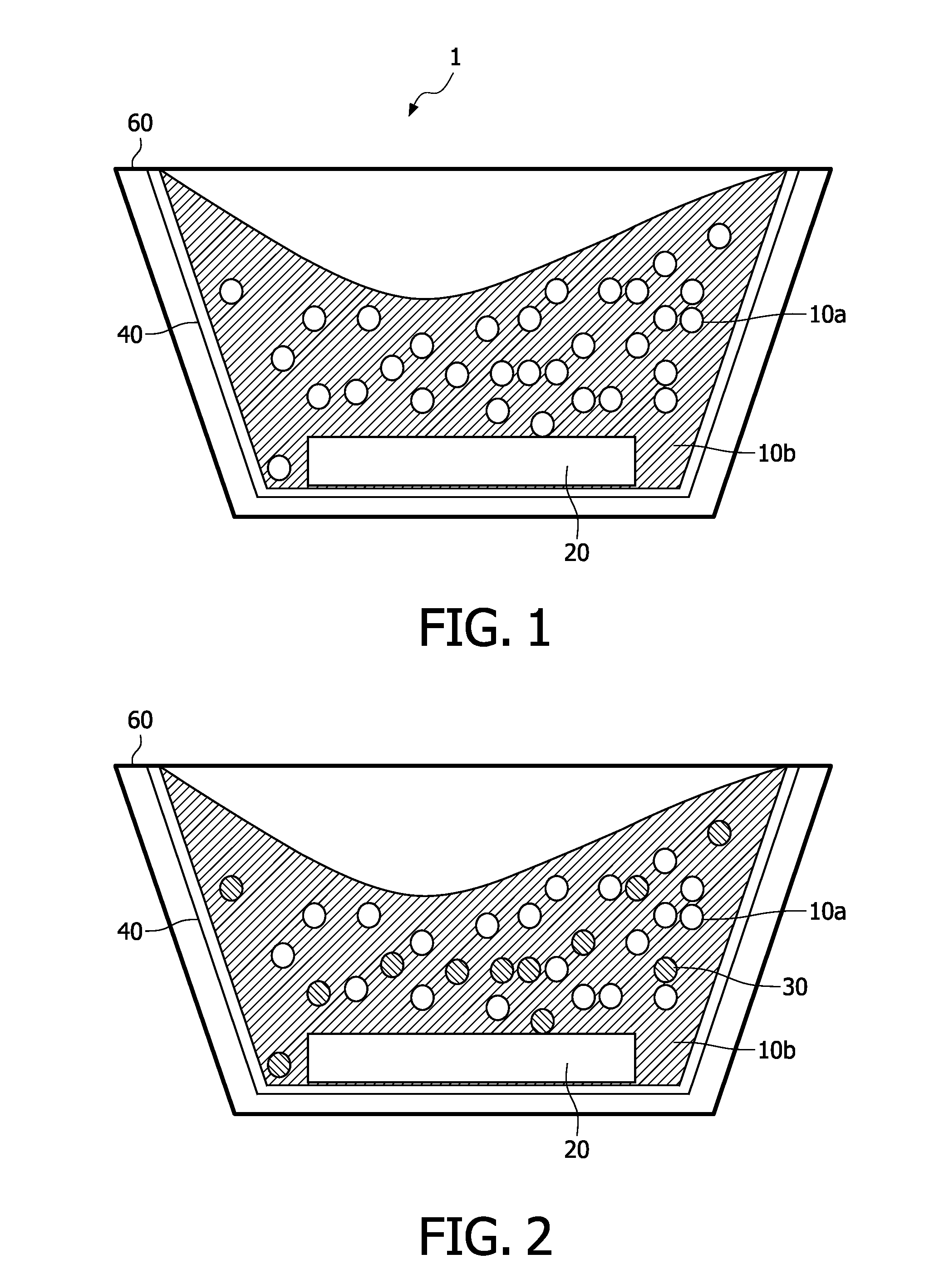
The invention relates to an illumination system with a material having a low or negative thermal expansion coefficient in order to compensate for the thermal expansion of the further materials present in the illumination system.
Description
FIELD OF THE INVENTION[0001]The present invention is directed to novel materials for light emitting devices, especially to the field of novel materials for LEDsBACKGROUND OF THE INVENTION[0002]Phosphor converted light emitting diodes (pcLEDs) are based on a blue or UV light emitting die, which is usually made out of (AlInGa)N and at least one luminescent layer, which is usually deposited onto the chip as a silicone suspension.[0003]In order to emit white light, usually blue-emitting (In,Ga)N LEDs are converted into white light emitting LEDs either by a yellow-orange phosphor (e.g. YAG:Ce) or by a two component phosphor blend, containing a yellow- and a red-emitting one.[0004]An alternative second approach is presently applied to achieve warm-white LEDs, whereby the employed phosphors are YAG:Ce in a blend with a red emitting material comprising Eu2+ in a covalent lattice, e.g. (Ca,Sr)S:Eu, CaAlSiN3:Eu, or (Ba,Sr,Ca)2Si5N8:Eu.[0005]Especially the reliability of phosphor converted LED...
Claims
Login to View More Application Information
Patent Timeline
 Patent Type & AuthorityApplications(United States)
IPC IPC(8): H01L33/00H01L33/50H01L33/54
CPCC04B35/44H01L33/54C04B35/472C04B35/495C04B2235/3203C04B2235/3222C04B2235/3224C04B2235/3225C04B2235/3227C04B2235/3229C04B2235/3244C04B2235/3256C04B2235/326C04B2235/764C04B2235/9653C09K11/7774C09K11/7794F21K9/00H01L33/501H01L33/502C04B35/447F21K9/64
InventorJUESTEL, THOMASRONDA, CORNELIS REINDER
OwnerKONINKLIJKE PHILIPS ELECTRONICS NV