

Pinless power coupling
a power coupling and pinless technology, applied in the direction of transformer/inductance details, circuit arrangements, inductances, etc., can solve the problems of pin insertion difficulty, mains socket injury risk, and electrical power jacks cannot be located on surfaces
- Summary
- Abstract
- Description
- Claims
- Application Information
AI Technical Summary
Benefits of technology
Problems solved by technology
Method used
Image

Examples
first embodiment
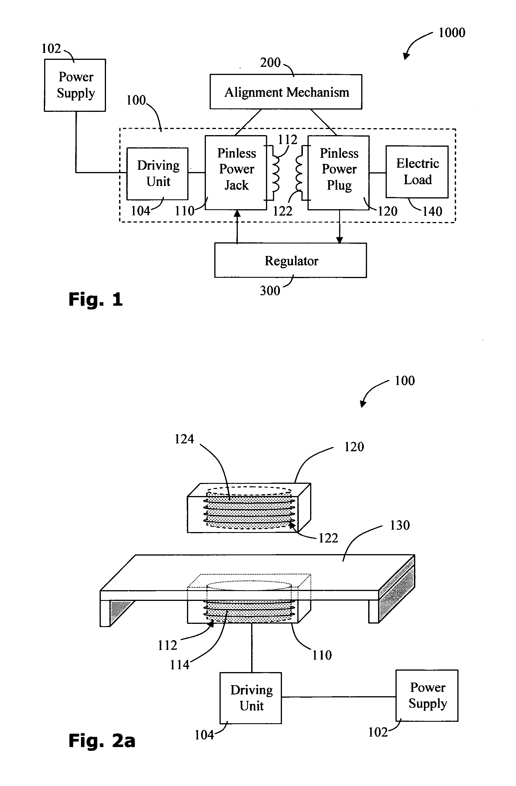
[0089]Reference is now made to FIG. 1 which is a 1000 for pinlessly providing power to an electric load 140, according to the invention. The power transfer system 1000 includes a pinless power coupling 100, an alignment mechanism 200 and a power, regulator 300.
[0090]The pinless power coupling 100 comprises a pinless power jack 110 and a pinless power plug 120. The pinless power jack 110 includes a primary inductive coil 112 wired to a power supply 102 via a driving unit 104. The pinless power plug 120 includes a secondary inductive coil 122 which is wired to the electric load 140. When the secondary coil 122 is brought close to the primary coil 112 and a variable voltage is applied to the primary coil 112 by the driving unit 104, power may be transferred between the coils by electromagnetic induction.
[0091]The alignment mechanism 200 is provided to facilitate aligning the primary coil 112 with the secondary coil 122 which improves the efficiency of the inductive coupling. The regula...
second embodiment
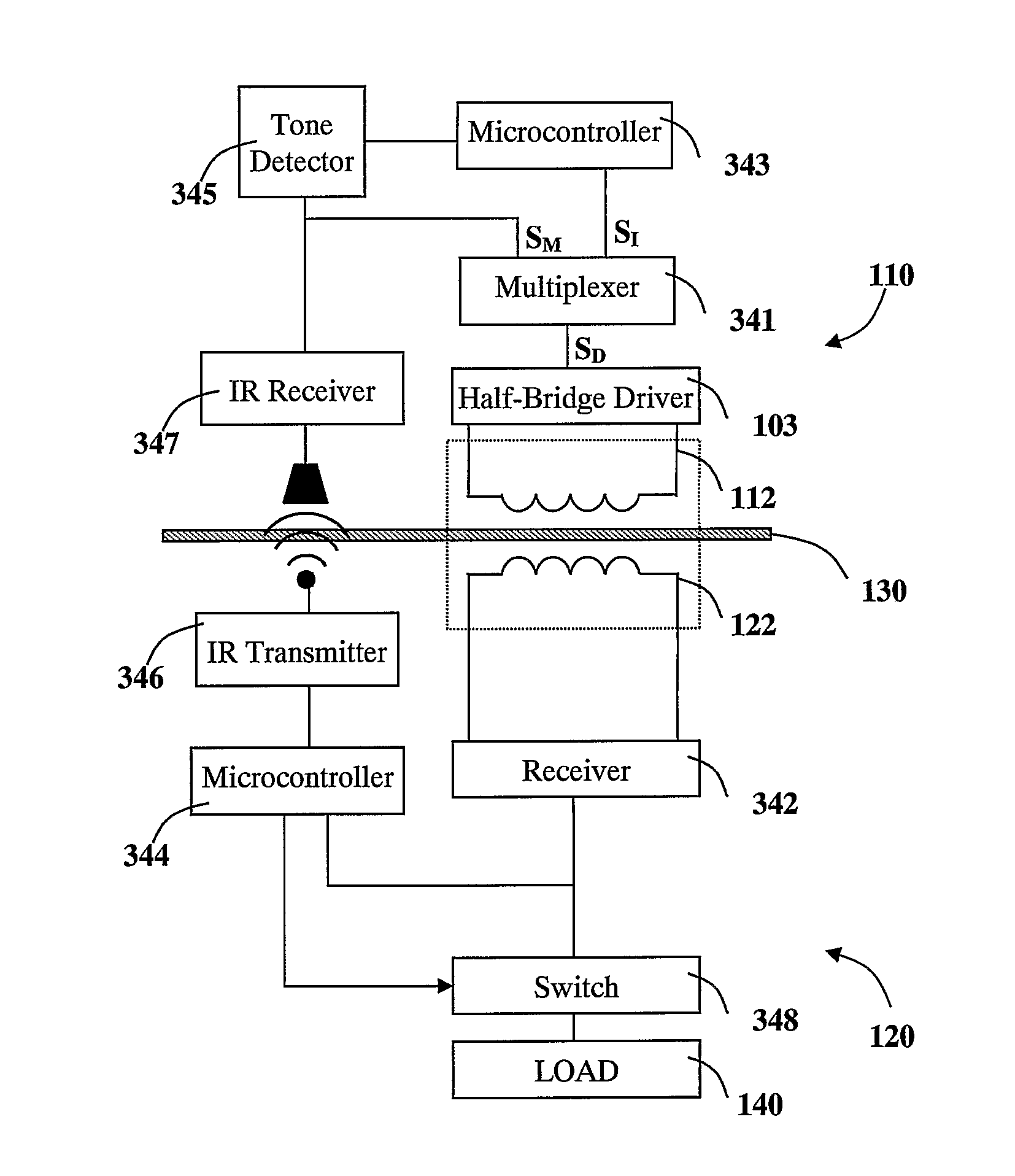
[0093]Reference is now made to FIG. 2a which shows a pinless power coupling 100 according to the invention. A pinless power jack 110, which may be incorporated into a substantially flat surface 130 for example, is couplable with a pinless power plug 120. The pinless power jack 110 includes an annular primary coil 112 shielded behind an insulating layer, which may be hardwired to a power source 102 via a driving unit 104. Driving electronics may include a switching unit providing a high frequency oscillating voltage supply, for example.
[0094]The pinless power plug 120 includes an annular secondary coil 122 that is configured to inductively couple with the primary coil 112 of the pinless power jack 110 to form a power transferring couple that is essentially a transformer. Optionally, a primary ferromagnetic core 114 is provided in the pinless power jack 110 and a secondary ferromagnetic core 124 is provided in the pinless power plug 120 to improve energy transfer efficiency.
[0095]It w...
third embodiment
[0104]FIGS. 3a and 3b schematically represent an exemplary induction coil 1200, according to the invention in schematic and exploded views respectively. The induction coil 1200 is annular in form and is suitable for use as a primary coil 112 in a pinless power jack 110 or for use as a secondary coil 122 in a pinless power plug 120. The coil is noted to provide a particularly good coupling for its overall size. An induction coil 1200 is formed by stacking a plurality of conducting rings 1202a-e upon a base board 1214. The induction coil 1200 is in contact with two point contacts 1212a, 1212b upon the base board 1214. Each conducting ring 1202 has a leading protruding contact 1208 and a trailing protruding contact 1206 which protrude radially from the center of a split ring 1204 and are located on either side of insulating gap 1210.
[0105]The conducting rings 1202a-e are stacked in such a manner that each ring is insulated from the rings adjacent to it. The insulating gaps 1210 in the ...
PUM
 Abstract
Description
Claims
Application Information