Solid state illumination system

a lighting system and solid state technology, applied in the direction of optical radiation measurement, instruments, spectrometry/spectrophotometry/monochromators, etc., can solve the problems of inability to extend the control of the lcd, circuits with limited applications, and inability to achieve energy saving and energy saving. , to achieve the effect of reducing unnecessary power consumption

Inactive Publication Date: 2010-07-22
SHARP KK
View PDF11 Cites 170 Cited by
  • Summary
  • Abstract
  • Description
  • Claims
  • Application Information

AI Technical Summary

Benefits of technology

[0044]It reduces unnecessary power consum

Problems solved by technology

However, this is not an energy efficient method as the CCD is a powered light detector and consumes battery life.
This circuit has limited applications and can only be used in passive backlight devices (such as a backlight in remote controls or k

Method used


Image

  • Solid state illumination system
  • Solid state illumination system
  • Solid state illumination system

Examples


first embodiment

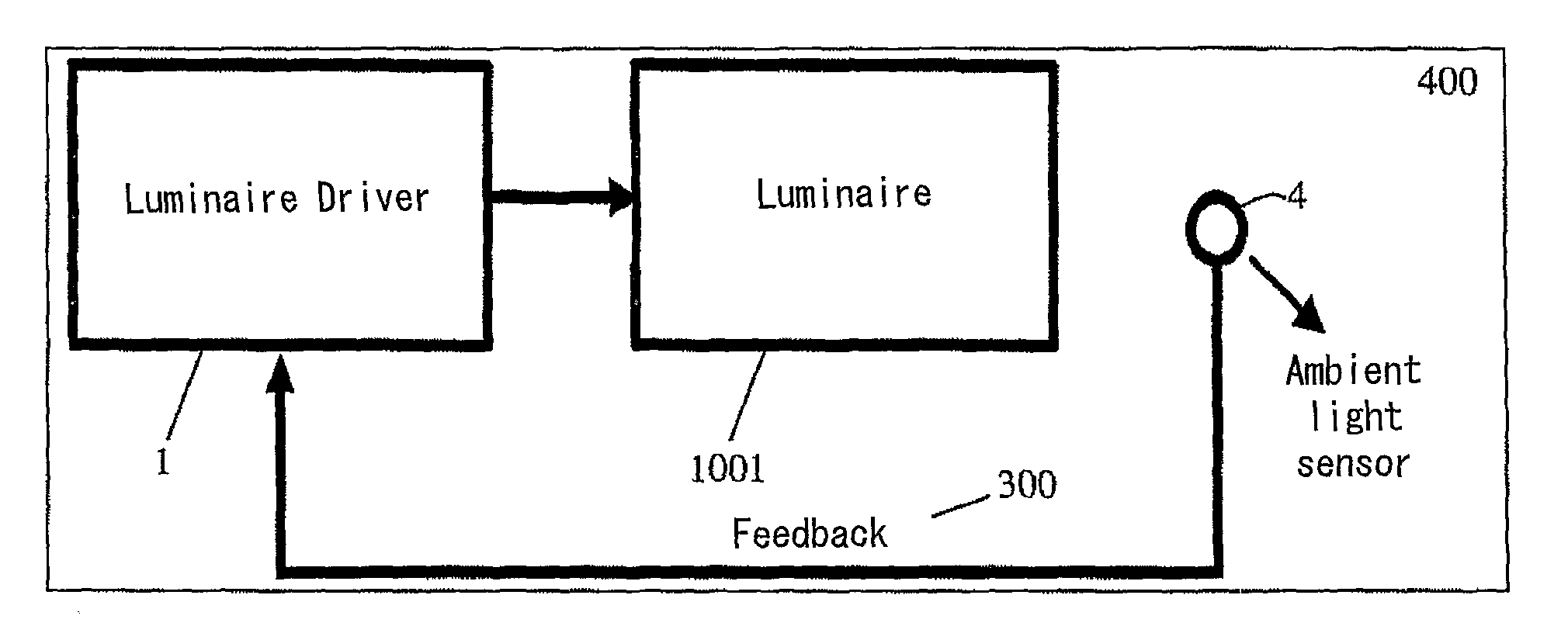
[0073]FIG. 11 shows a block schematic diagram of an illumination system according to the invention. In this embodiment an illumination system which automatically adjusts its output emission according to the changes in the ambient light levels is disclosed. Here the illumination system consists of a light-emitting portion 10 comprising two or more light sources, for example, two or more solid state light sources such as LEDs, which, according to the bias applied across the light source, act either as an emitter or as an ambient light sensor. (Embodiments of the invention will be described using LEDs as the light sources, but the invention is not limited to this.)

[0074]In FIG. 11, the light-emitting portion 10 of the illumination system is connectable to a detection circuit 13 by a first switch 11 or to a driving circuit 16 by a second switch 12. The first and second switches 11, 12 may be operated by a suitable control means (as described below with reference to FIG. 12). When switch...

second embodiment

[0091]FIG. 12 shows a schematic block diagram of the invention, in which multiple LEDs can be arranged to act as both light emitters and detectors, in the general manner shown in FIG. 5.

[0092]FIG. 12 shows three LEDs 101, 102, 103 one of each of the three primary colours (red, green and blue), but the embodiment is not limited to this. It would also be possible to use fewer than three colours or to use more than three colours. Moreover, although FIG. 12 shows one LED of each colour, multiple LEDs of each colour can be used, arranged in either parallel or series to provide a desired output intensity. (References herein to a “blue LED”, “green LED”, etc, are intended to cover the case of a plurality of identical blue (or green, etc) LEDs connected so as to provide a desired output intensity in addition to the case of a single LED.) In a case where multiple LEDs of one colour are arranged in series, the bias voltages V1 and V2 are adjusted according to the number of LEDs in series.

[009...


PUM


Abstract

An illumination system comprises at least two light sources (101,102,103) having different emission spectra to one another; a detection circuit (131,132,133) for sensing a light intensity using at least one of the light sources as a photosensor; and driving means (161,162,163) for driving the light source in dependence on the sensed spectral distribution of light. The emission spectrum of a light source with the smallest bandgap overlaps the emission spectrum of a light source with the second-smallest bandgap. The illumination system is possible to measure the intensity of light emitted by the light source with the smallest bandgap by putting the light source with the second-smallest bandgap in detection mode. The illumination system may also sense the spectral distribution of ambient light, to allow the output from the illumination system to be adjusted in dependence on the ambient light.

Description

TECHNICAL FIELD[0001]The present invention relates to Solid State Lighting (SSL) systems, and in particular to those which employ red, blue and green LEDs, phosphor converted White Light Emitting Diodes (WLEDs), or hybrid laser-LED-phosphor based light emitters. The proposed SSL system can be used in various lighting applications such as, for example, camera flash, therapy luminaires, adaptive and mood lights, traffic signals, signage, decorative illumination, corridor lights, street lights displays, etc. . . . For example, effective power management for reduced battery consumption is important for portable light sources, such as a camera mobile phone, where a plurality of phosphor converted WLEDs or individual coloured LEDs, are used as a flash for subject illumination.[0002]SSL systems promise energy efficient, cost effective and flexible alternatives to conventional lighting methods where usually an incandescent bulb or a fluorescent lamp is used.BACKGROUND ART[0003]An illuminati...

Claims


Application Information

Patent Timeline
IPC IPC(8): G09G5/00H05B37/02H05B39/00H05B44/00
CPCG01J1/32G01J1/4204G01J3/10G01J3/50G01J3/505H05B33/0857H05B33/0869H05B33/0872H05B45/22G09G3/3413H05B45/00
Inventor ROSHAN, RAKESHHADWEN, BENJAMIN JAMESMONTGOMERY, DAVID JAMESHEFFERNAN, JONATHAN
Owner SHARP KK
Why Eureka
Try Eureka